正在加载图片...

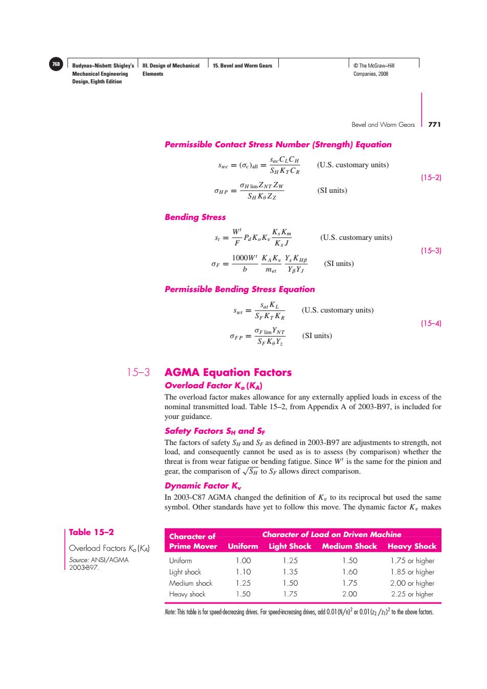
Budynas-Nisbett:Shigley's lll.Design of Mechanical 15.Bevel and Worm Gears T©The McGraw-Hill Mechanical Engineering Elements Companies,2008 Design,Eighth Edition Bevel and Worm Gears 771 Permissible Contact Stress Number(Strength)Equation SaeCLCH Swc (c)all SHKTCR (U.S.customary units) (15-2) OH limZNT ZW OHP= (SI units) SH KeZz Bending Stress W KsKm S1= Pakak.K:J (U.S.customary units) (15-3) OF= 1000W KAK Yx KHB (SI units) b met YBYJ Permissible Bending Stress Equation SatKL Swt= (U.S.customary units) SEKTKR (15-4 OFlimYNT OFP= (SI units) SEKaY, 15-3 AGMA Equation Factors Overload Factor Ko(KA) The overload factor makes allowance for any externally applied loads in excess of the nominal transmitted load.Table 15-2,from Appendix A of 2003-B97,is included for your guidance. Safety Factors SH and Se The factors of safety Su and Se as defined in 2003-B97 are adjustments to strength,not load,and consequently cannot be used as is to assess (by comparison)whether the threat is from wear fatigue or bending fatigue.Since W is the same for the pinion and gear,the comparison ofS to Sr allows direct comparison. Dynamic Factor Ky In 2003-C87 AGMA changed the definition of K to its reciprocal but used the same symbol.Other standards have yet to follow this move.The dynamic factor K makes Table 15-2 Character of Character of Load on Driven Machine ○verload Factors K(KA) Prime Mover Uniform Light Shock Medium Shock Heavy Shock Source:ANSI/AGMA Uniform 1.00 1.25 1.50 1.75 or higher 2003B97. Light shock 110 1.35 1.60 1.85 or higher Medium shock 1.25 1.50 1.75 2.00 or higher Heavy shock 1.50 1.75 2.00 2.25 or higher Note:This table is for speed-decreasing drives.For speed-increasing drives,odd 0.01(N/n)or0.01(z2/)to the above factors.Budynas−Nisbett: Shigley’s Mechanical Engineering Design, Eighth Edition III. Design of Mechanical Elements 15. Bevel and Worm Gears 768 © The McGraw−Hill Companies, 2008 Bevel and Worm Gears 771 Permissible Contact Stress Number (Strength) Equation swc = (σc)all = sacCLCH SH KTCR (U.S. customary units) σH P = σH lim ZN T ZW SH Kθ ZZ (SI units) (15–2) Bending Stress st = Wt F PdKoKv KsKm Kx J (U.S. customary units) σF = 1000Wt b KAKv met Yx K Hβ YβYJ (SI units) (15–3) Permissible Bending Stress Equation swt = sat KL SF KT KR (U.S. customary units) σF P = σF limYN T SF KθYz (SI units) (15–4) 15–3 AGMA Equation Factors Overload Factor Ko (KA) The overload factor makes allowance for any externally applied loads in excess of the nominal transmitted load. Table 15–2, from Appendix A of 2003-B97, is included for your guidance. Safety Factors SH and SF The factors of safety SH and SF as defined in 2003-B97 are adjustments to strength, not load, and consequently cannot be used as is to assess (by comparison) whether the threat is from wear fatigue or bending fatigue. Since Wt is the same for the pinion and gear, the comparison of √SH to SF allows direct comparison. Dynamic Factor Kv In 2003-C87 AGMA changed the definition of Kv to its reciprocal but used the same symbol. Other standards have yet to follow this move. The dynamic factor Kv makes Table 15–2 Overload Factors Ko (KA) Source: ANSI/AGMA 2003-B97. Character of Character of Load on Driven Machine Prime Mover Uniform Light Shock Medium Shock Heavy Shock Uniform 1.00 1.25 1.50 1.75 or higher Light shock 1.10 1.35 1.60 1.85 or higher Medium shock 1.25 1.50 1.75 2.00 or higher Heavy shock 1.50 1.75 2.00 2.25 or higher Note: This table is for speed-decreasing drives. For speed-increasing drives, add 0.01(N/n)2 or 0.01(z2 /z1) 2 to the above factors