正在加载图片...

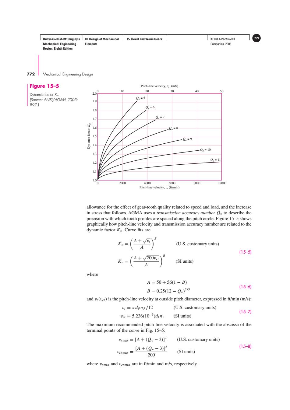
Budynas-Nisbett:Shigley's Ill.Design of Mechanical 15.Bevel and Worm Gears T©The McGraw-Hill 769 Mechanical Engineering Elements Companies,2008 Design,Eighth Edition 772 Mechanical Engineering Design Figure 15-5 Pitch-line velocity.(m/s) 20 10 20 30 40 50 Dynamic factor Kv. (Source:ANSI/AGMA 2003- 2。=5 1.9 B97.J Q=6 1.7 0=7 1.6 2n=8 1.5 2。=9 1.4 Q。=10 13 1.2 g=11 2000 4000 6000 8000 10000 Pitch-line velocity.(ft/min) allowance for the effect of gear-tooth quality related to speed and load,and the increase in stress that follows.AGMA uses a transmission accuracy number to describe the precision with which tooth profiles are spaced along the pitch circle.Figure 15-5 shows graphically how pitch-line velocity and transmission accuracy number are related to the dynamic factor K.Curve fits are Kp= A+√: A (U.S.customary units) (15-5) K。= A+√200ve: (SI units) A where A=50+56(1-B) (15-6) B=0.25(12-Q)2B and v:(ver)is the pitch-line velocity at outside pitch diameter,expressed in ft/min (m/s): =πdpnr/12 (U.S.customary units) (15-7刀 vau=5.236(10-5)dn1 (SI units) The maximum recommended pitch-line velocity is associated with the abscissa of the terminal points of the curve in Fig.15-5: 4max=[A+(Qw-3)]2 (U.S.customary units) [A+(2。-3)2 (15-8) Vte max (SI units) 200 where vrmax and ver max are in ft/min and m/s,respectively.Budynas−Nisbett: Shigley’s Mechanical Engineering Design, Eighth Edition III. Design of Mechanical Elements 15. Bevel and Worm Gears © The McGraw−Hill 769 Companies, 2008 772 Mechanical Engineering DesignDynamic factor, Kv Pitch-line velocity, vt (ft/min) Pitch-line velocity, vet (m/s) 0 2000 4000 6000 8000 10 000 0 10 20 30 40 50 1.0 1.1 1.2 1.3 1.4 1.5 1.6 1.7 1.8 1.9 2.0 Qv = 5 Qv = 7 Qv = 6 Qv = 8 Qv = 9 Qv = 10 Qv = 11 Figure 15–5 Dynamic factor Kv. (Source: ANSI/AGMA 2003- B97.) allowance for the effect of gear-tooth quality related to speed and load, and the increase in stress that follows. AGMA uses a transmission accuracy number Qv to describe the precision with which tooth profiles are spaced along the pitch circle. Figure 15–5 shows graphically how pitch-line velocity and transmission accuracy number are related to the dynamic factor Kv . Curve fits are Kv = A + √vt A B (U.S. customary units) Kv = A + √200vet A B (SI units) (15–5) where A = 50 + 56(1 − B) B = 0.25(12 − Qv) 2/3 (15–6) and vt(vet) is the pitch-line velocity at outside pitch diameter, expressed in ft/min (m/s): vt = πdPnP/12 (U.S. customary units) vet = 5.236(10−5 )d1n1 (SI units) (15–7) The maximum recommended pitch-line velocity is associated with the abscissa of the terminal points of the curve in Fig. 15–5: vt max = [A + (Qv − 3)] 2 (U.S. customary units) vte max = [A + (Qv − 3)] 2 200 (SI units) (15–8) where vt max and vet max are in ft/min and m/s, respectively.����