正在加载图片...
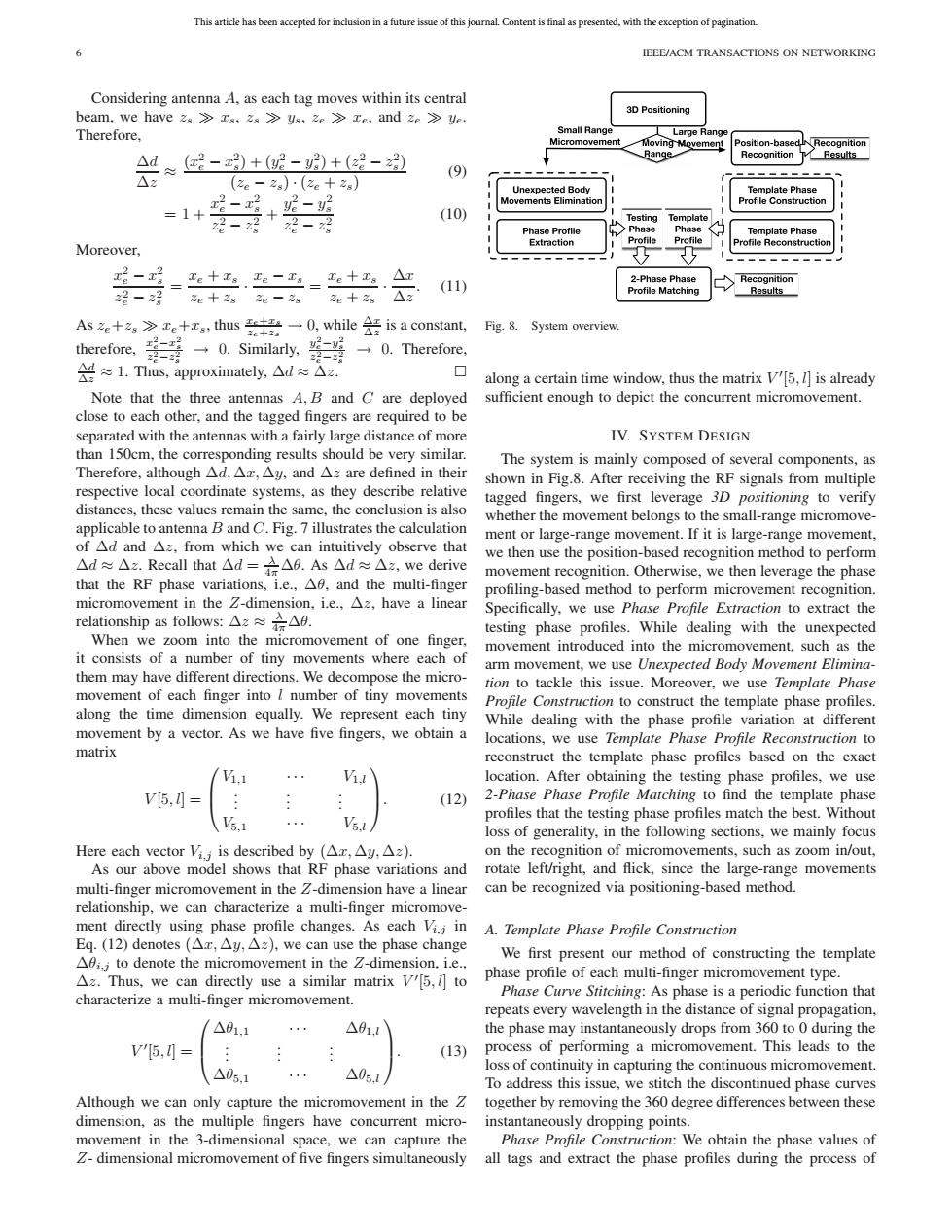
This article has been accepted for inclusion in a future issue of this journal.Content is final as presented,with the exception of pagination. IEEE/ACM TRANSACTIONS ON NETWORKING Considering antenna A,as each tag moves within its central beam,we have 2s≥xg,zs>ys,ze≥xe,and ze≥e 3D Positioning Therefore, Small Rang Large Range Moving Movement Position-based. Recognition A4≈好-)+妮-+(-边 Range Recognition Results (9 △z (2e-za)·(2e+2s) Unexpected Body Template Phase Movements Elimination Profile Construction =1+ (10) Template 2径-2 2-2 Testing Phase Profile Template Phase Moreover, Extraction Profile Reconstructior - ,=e十工.e-= Te十Ts△T 2-Phase Phas (11) 诏一 Matchin 2e十2s2e-2s Ze 2a 2 Asze+za>re+zg,thus#→0,while¥is a constant, Fig.8.System overview 2e十2。 therefore,-号 Ie-zi →0.Similarly,g 22-2图 →O.Therefore, 是≈1.Thus,approximately,.△d≈△2z. ◇ along a certain time window,thus the matrix V[5,l]is already Note that the three antennas A,B and C are deployed sufficient enough to depict the concurrent micromovement. close to each other.and the tagged fingers are required to be separated with the antennas with a fairly large distance of more IV.SYSTEM DESIGN than 150cm,the corresponding results should be very similar. The system is mainly composed of several components,as Therefore,although△d,△x,△y,and△e are defined in their shown in Fig.8.After receiving the RF signals from multiple respective local coordinate systems,as they describe relative tagged fingers,we first leverage 3D positioning to verify distances,these values remain the same,the conclusion is also whether the movement belongs to the small-range micromove- applicable to antenna B and C.Fig.7 illustrates the calculation ment or large-range movement.If it is large-range movement, of Ad and Az,from which we can intuitively observe that we then use the position-based recognition method to perform △d≈△z.Recall that△d=△A.As△d≈△z,we derive movement recognition.Otherwise,we then leverage the phase that the RF phase variations,i.e.,A,and the multi-finger profiling-based method to perform microvement recognition. micromovement in the Z-dimension,i.e.,Az,have a linear Specifically,we use Phase Profile Extraction to extract the relationship as follows:△z≈六△9. testing phase profiles.While dealing with the unexpected When we zoom into the micromovement of one finger, movement introduced into the micromovement,such as the it consists of a number of tiny movements where each of arm movement,we use Unexpected Body Movement Elimina- them may have different directions.We decompose the micro- tion to tackle this issue.Moreover,we use Template Phase movement of each finger into I number of tiny movements Profile Construction to construct the template phase profiles. along the time dimension equally.We represent each tiny While dealing with the phase profile variation at different movement by a vector.As we have five fingers,we obtain a locations,we use Template Phase Profile Reconstruction to matrix reconstruct the template phase profiles based on the exact location.After obtaining the testing phase profiles,we use V[5, (12) 2-Phase Phase Profile Matching to find the template phase profiles that the testing phase profiles match the best.Without V5 loss of generality,in the following sections,we mainly focus Here each vector Vi,is described by(△x,△y,△z). on the recognition of micromovements,such as zoom in/out, As our above model shows that RF phase variations and rotate left/right,and flick,since the large-range movements multi-finger micromovement in the 2-dimension have a linear can be recognized via positioning-based method. relationship,we can characterize a multi-finger micromove- ment directly using phase profile changes.As each Vi.j in A.Template Phase Profile Construction Eq.(l2)denotes(△xr,△y,△z,we can use the phase change A0i;to denote the micromovement in the Z-dimension,i.e., We first present our method of constructing the template Az.Thus,we can directly use a similar matrix V[5,l]to phase profile of each multi-finger micromovement type. characterize a multi-finger micromovement. Phase Curve Stitching:As phase is a periodic function that repeats every wavelength in the distance of signal propagation, △01.1 △01.1 the phase may instantaneously drops from 360 to 0 during the V'[5,I= 13) process of performing a micromovement.This leads to the △05.1 loss of continuity in capturing the continuous micromovement. To address this issue,we stitch the discontinued phase curves Although we can only capture the micromovement in the Z together by removing the 360 degree differences between these dimension,as the multiple fingers have concurrent micro- instantaneously dropping points. movement in the 3-dimensional space,we can capture the Phase Profile Construction:We obtain the phase values of 2-dimensional micromovement of five fingers simultaneously all tags and extract the phase profiles during the process ofThis article has been accepted for inclusion in a future issue of this journal. Content is final as presented, with the exception of pagination. 6 IEEE/ACM TRANSACTIONS ON NETWORKING Considering antenna A, as each tag moves within its central beam, we have zs xs, zs ys, ze xe, and ze ye. Therefore, Δd Δz ≈ (x2 e − x2 s)+(y2 e − y2 s )+(z2 e − z2 s ) (ze − zs) · (ze + zs) (9) = 1+ x2 e − x2 s z2 e − z2 s + y2 e − y2 s z2 e − z2 s (10) Moreover, x2 e − x2 s z2 e − z2 s = xe + xs ze + zs · xe − xs ze − zs = xe + xs ze + zs · Δx Δz . (11) As ze+zs xe+xs, thus xe+xs ze+zs → 0, while Δx Δz is a constant, therefore, x2 e−x2 s z2 e−z2 s → 0. Similarly, y2 e−y2 s z2 e−z2 s → 0. Therefore, Δd Δz ≈ 1. Thus, approximately, Δd ≈ Δz. Note that the three antennas A, B and C are deployed close to each other, and the tagged fingers are required to be separated with the antennas with a fairly large distance of more than 150cm, the corresponding results should be very similar. Therefore, although Δd, Δx, Δy, and Δz are defined in their respective local coordinate systems, as they describe relative distances, these values remain the same, the conclusion is also applicable to antenna B and C. Fig. 7 illustrates the calculation of Δd and Δz, from which we can intuitively observe that Δd ≈ Δz. Recall that Δd = λ 4π Δθ. As Δd ≈ Δz, we derive that the RF phase variations, i.e., Δθ, and the multi-finger micromovement in the Z-dimension, i.e., Δz, have a linear relationship as follows: Δz ≈ λ 4πΔθ. When we zoom into the micromovement of one finger, it consists of a number of tiny movements where each of them may have different directions. We decompose the micromovement of each finger into l number of tiny movements along the time dimension equally. We represent each tiny movement by a vector. As we have five fingers, we obtain a matrix V [5, l] = ⎛ ⎜⎝ V1,1 ··· V1,l . . . . . . . . . V5,1 ··· V5,l ⎞ ⎟⎠. (12) Here each vector Vi,j is described by (Δx, Δy, Δz). As our above model shows that RF phase variations and multi-finger micromovement in the Z-dimension have a linear relationship, we can characterize a multi-finger micromovement directly using phase profile changes. As each Vi,j in Eq. (12) denotes (Δx, Δy, Δz), we can use the phase change Δθi,j to denote the micromovement in the Z-dimension, i.e., Δz. Thus, we can directly use a similar matrix V [5, l] to characterize a multi-finger micromovement. V [5, l] = ⎛ ⎜⎝ Δθ1,1 ··· Δθ1,l . . . . . . . . . Δθ5,1 ··· Δθ5,l ⎞ ⎟⎠. (13) Although we can only capture the micromovement in the Z dimension, as the multiple fingers have concurrent micromovement in the 3-dimensional space, we can capture the Z- dimensional micromovement of five fingers simultaneously Fig. 8. System overview. along a certain time window, thus the matrix V [5, l] is already sufficient enough to depict the concurrent micromovement. IV. SYSTEM DESIGN The system is mainly composed of several components, as shown in Fig.8. After receiving the RF signals from multiple tagged fingers, we first leverage 3D positioning to verify whether the movement belongs to the small-range micromovement or large-range movement. If it is large-range movement, we then use the position-based recognition method to perform movement recognition. Otherwise, we then leverage the phase profiling-based method to perform microvement recognition. Specifically, we use Phase Profile Extraction to extract the testing phase profiles. While dealing with the unexpected movement introduced into the micromovement, such as the arm movement, we use Unexpected Body Movement Elimination to tackle this issue. Moreover, we use Template Phase Profile Construction to construct the template phase profiles. While dealing with the phase profile variation at different locations, we use Template Phase Profile Reconstruction to reconstruct the template phase profiles based on the exact location. After obtaining the testing phase profiles, we use 2-Phase Phase Profile Matching to find the template phase profiles that the testing phase profiles match the best. Without loss of generality, in the following sections, we mainly focus on the recognition of micromovements, such as zoom in/out, rotate left/right, and flick, since the large-range movements can be recognized via positioning-based method. A. Template Phase Profile Construction We first present our method of constructing the template phase profile of each multi-finger micromovement type. Phase Curve Stitching: As phase is a periodic function that repeats every wavelength in the distance of signal propagation, the phase may instantaneously drops from 360 to 0 during the process of performing a micromovement. This leads to the loss of continuity in capturing the continuous micromovement. To address this issue, we stitch the discontinued phase curves together by removing the 360 degree differences between these instantaneously dropping points. Phase Profile Construction: We obtain the phase values of all tags and extract the phase profiles during the process of����