正在加载图片...

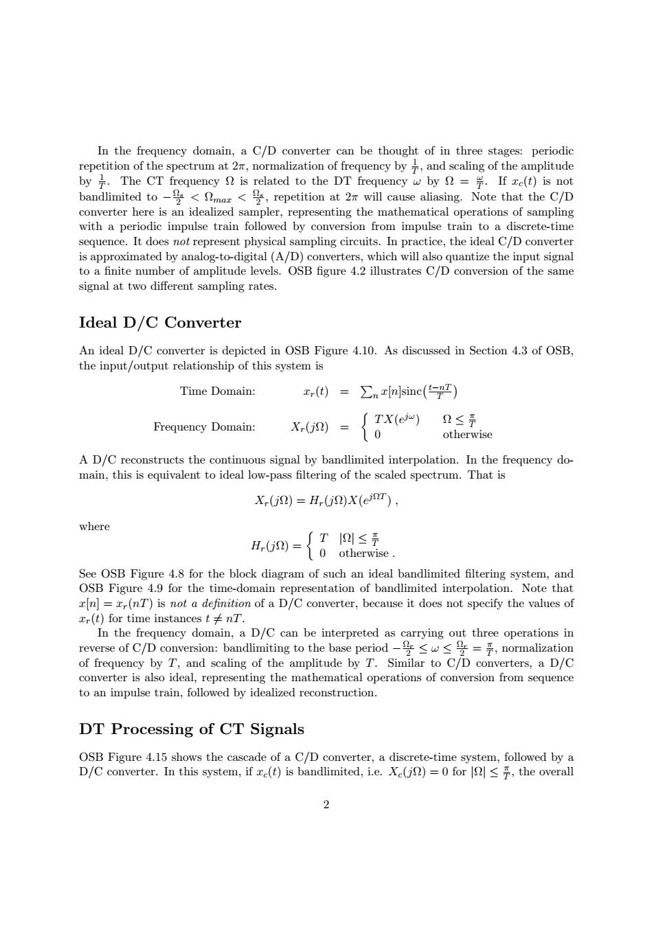
In the frequency domain,a C/D converter can be thought of in three stages:periodic repetition of the spectrum at 2n,normalization of frequency by and scaling of the amplitude by The CT frequency is related to the DT frequency w by =If xe(t)is not bandlimited to<maz<,repetition at 2r will cause aliasing.Note that the C/D converter here is an idealized sampler,representing the mathematical operations of sampling with a periodic impulse train followed by conversion from impulse train to a discrete-time sequence.It does not represent physical sampling circuits.In practice,the ideal C/D converter is approximated by analog-to-digital(A/D)converters,which will also quantize the input signal to a finite number of amplitude levels.OSB figure 4.2 illustrates C/D conversion of the same signal at two different sampling rates. Ideal D/C Converter An ideal D/C converter is depicted in OSB Figure 4.10.As discussed in Section 4.3 of OSB, the input/output relationship of this system is Time Domain: x(t)= ∑xnsinc((-n平) ∫TX(eu) D≤开 Frequency Domain: X(j2) 10 otherwise A D/C reconstructs the continuous signal by bandlimited interpolation.In the frequency do- main,this is equivalent to ideal low-pass filtering of the scaled spectrum.That is X,(j2)=H,(j)X(er), where ∫T≤票 ()=0otherwise. See OSB Figure 4.8 for the block diagram of such an ideal bandlimited filtering system,and OSB Figure 4.9 for the time-domain representation of bandlimited interpolation.Note that x[n]=x(nT)is not a definition of a D/C converter,because it does not specify the values of xr(t)for time instances t nT. In the frequency domain,a D/C can be interpreted as carrying out three operations in reverse of C/D conversion:bandlimiting to the base period-号≤w≤号=,normalization of frequency by T,and scaling of the amplitude by T.Similar to C/D converters,a D/C converter is also ideal,representing the mathematical operations of conversion from sequence to an impulse train,followed by idealized reconstruction. DT Processing of CT Signals OSB Figure 4.15 shows the cascade of a C/D converter,a discrete-time system,followed by a D/C converter.In this system,if ce(t)is bandlimited,i.e.Xe(js)=0 for <the overall 2� In the frequency domain, a C/D converter can be thought of in three stages: periodic 1 repetition of the spectrum at 2π, normalization of frequency by T , and scaling of the amplitude by 1 . The CT frequency Ω is related to the DT frequency ω by Ω = ω . If xc(t) is not T T bandlimited to −Ωs < Ωmax < Ω 2 s 2 , repetition at 2π will cause aliasing. Note that the C/D converter here is an idealized sampler, representing the mathematical operations of sampling with a periodic impulse train followed by conversion from impulse train to a discrete-time sequence. It does not represent physical sampling circuits. In practice, the ideal C/D converter is approximated by analog-to-digital (A/D) converters, which will also quantize the input signal to a finite number of amplitude levels. OSB figure 4.2 illustrates C/D conversion of the same signal at two different sampling rates. Ideal D/C Converter An ideal D/C converter is depicted in OSB Figure 4.10. As discussed in Section 4.3 of OSB, the input/output relationship of this system is Time Domain: xr(t) = � n x[n]sinc�t−nT � T π � T X(ejω Frequency Domain: X ) Ω ≤ T r(jΩ) = 0 otherwise A D/C reconstructs the continuous signal by bandlimited interpolation. In the frequency domain, this is equivalent to ideal low-pass filtering of the scaled spectrum. That is Xr(jΩ) = Hr(jΩ)X(ejΩT ) , where π H T r(jΩ) = � T |Ω| ≤ 0 otherwise . See OSB Figure 4.8 for the block diagram of such an ideal bandlimited filtering system, and OSB Figure 4.9 for the time-domain representation of bandlimited interpolation. Note that x[n] = xr(nT) is not a definition of a D/C converter, because it does not specify the values of xr(t) for time instances t = nT. In the frequency domain, a D/C can be interpreted as carrying out three operations in π reverse of C/D conversion: bandlimiting to the base period −Ω 2 r ≤ ω ≤ Ω 2 r = T , normalization of frequency by T, and scaling of the amplitude by T. Similar to C/D converters, a D/C converter is also ideal, representing the mathematical operations of conversion from sequence to an impulse train, followed by idealized reconstruction. DT Processing of CT Signals OSB Figure 4.15 shows the cascade of a C/D converter, a discrete-time system, followed by a π D/C converter. In this system, if xc(t) is bandlimited, i.e. Xc(jΩ) = 0 for |Ω| ≤ T , the overall 2