正在加载图片...
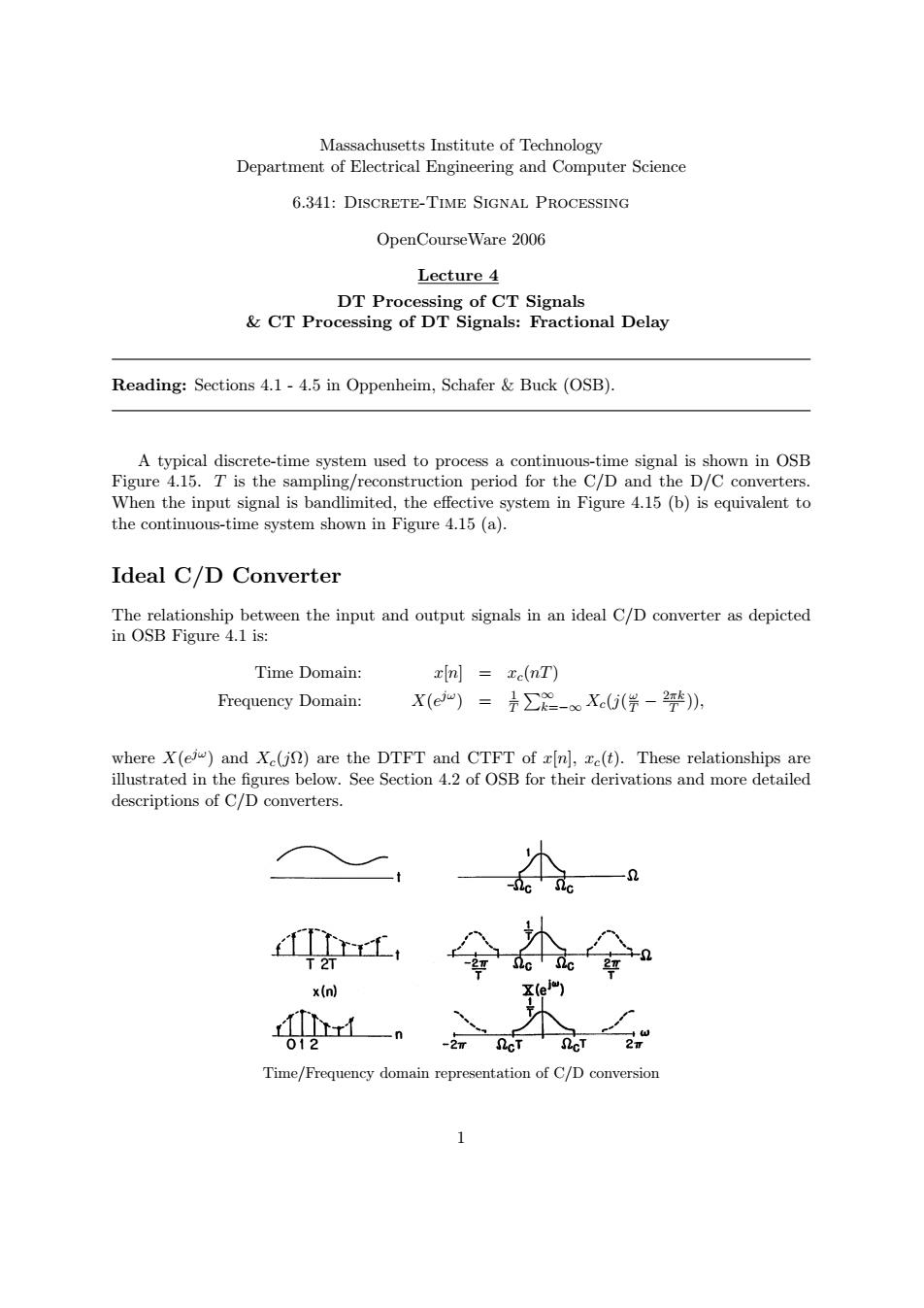
Massachusetts Institute of Technology Department of Electrical Engineering and Computer Science 6.341:DISCRETE-TIME SIGNAL PROCESSING OpenCourse Ware 2006 Lecture 4 DT Processing of CT Signals CT Processing of DT Signals:Fractional Delay Reading:Sections 4.1-4.5 in Oppenheim,Schafer Buck(OSB). A typical discrete-time system used to process a continuous-time signal is shown in OSB Figure 4.15.T is the sampling/reconstruction period for the C/D and the D/C converters. When the input signal is bandlimited,the effective system in Figure 4.15(b)is equivalent to the continuous-time system shown in Figure 4.15(a). Ideal C/D Converter The relationship between the input and output signals in an ideal C/D converter as depicted in OSB Figure 4.1 is: Time Domain: xin]xe(nT) Frequency Domain: X(e“)=是∑2-X0(学-钟)》, where X(ej)and Xe(jn)are the DTFT and CTFT of x[n],ze(t).These relationships are illustrated in the figures below.See Section 4.2 of OSB for their derivations and more detailed descriptions of C/D converters. x(n) 012 Time/Frequency domain representation of C/D conversionMassachusetts Institute of Technology Department of Electrical Engineering and Computer Science 6.341: Discrete-Time Signal Processing OpenCourseWare 2006 Lecture 4 DT Processing of CT Signals & CT Processing of DT Signals: Fractional Delay Reading: Sections 4.1 - 4.5 in Oppenheim, Schafer & Buck (OSB). A typical discrete-time system used to process a continuous-time signal is shown in OSB Figure 4.15. T is the sampling/reconstruction period for the C/D and the D/C converters. When the input signal is bandlimited, the effective system in Figure 4.15 (b) is equivalent to the continuous-time system shown in Figure 4.15 (a). Ideal C/D Converter The relationship between the input and output signals in an ideal C/D converter as depicted in OSB Figure 4.1 is: Time Domain: x[n] = xc(nT) Frequency Domain: X(ejω) = 1 T �∞ k=−∞ Xc(j( ω T − 2πk T )), where X(ejω) and Xc(jΩ) are the DTFT and CTFT of x[n], xc(t). These relationships are illustrated in the figures below. See Section 4.2 of OSB for their derivations and more detailed descriptions of C/D converters. Time/Frequency domain representation of C/D conversion 1