正在加载图片...
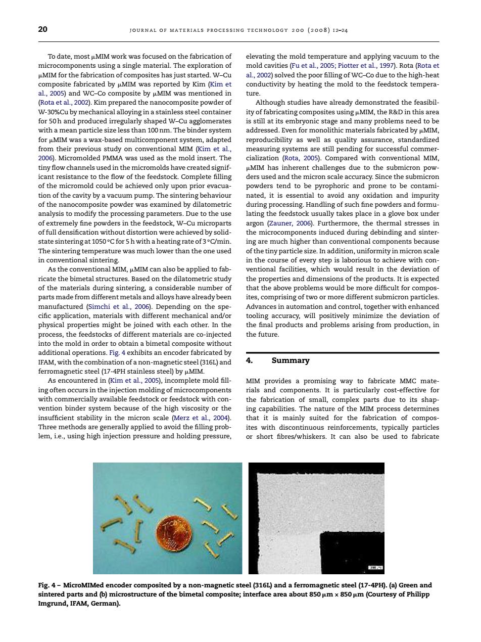
20 JOURNAL OF MATERIALS FROCESSING TECHNOLOGY 200 (2008)12-24 To date,most uMIM wor evatine the mold t th MMor the fabricaiofmehasedW-C k temper ture (Rota et Although studies have already demonstrated the feasibi with a mean particle size less.The binder system for Me was a wax multicomponent sys a0 2006.Mi romolded PMMA was used as the mold insert.The cialization(Rota,2005).Compared with conventional MIM moldshavecreatedsieni of the micromold could he achieved only upon prior evacua rophoric and prone to be contami tion of the cavity by a vacuum pump.The sintering behaviou pfthenawooayt nla s in the (Zauner,2006).Furthermore, chi omponen induced during The sintering to of the tiny In addition,uniformity in micron cale in conventional sintering icate the himetal structure appliedto ed on the dil cte siderable number o ha above problems would be more difficult for compos omp ith enh with dif m l and ooling accu cy.will positively minimize the deviation inal products and p blems arising from pro nto the mold in order to obtain a bimetal compo without .Fig.4 exhibits an en As encountered in (Kim et al.,2005),inc mplete mold fill MIM provides a promising way to fabricate MMC mate the ents. st-effec binder sv em h ause of the high viscosity or the ufficient stability in th 1.2004 is mainly suited for the fabrication lem,ie.,using high injection pressure and holding pr or short fbres/whiskers.It can as be used to fabricate Pig.4-MicroMIMed er netic steel (17-4PH (a)G Imgrund,IFAM,German)20 journal of materials processing technology 200 (2008) 12–24 To date, most MIM work was focused on the fabrication of microcomponents using a single material. The exploration of MIM for the fabrication of composites has just started. W–Cu composite fabricated by MIM was reported by Kim (Kim et al., 2005) and WC–Co composite by MIM was mentioned in (Rota et al., 2002). Kim prepared the nanocomposite powder of W-30%Cu by mechanical alloying in a stainless steel container for 50 h and produced irregularly shaped W–Cu agglomerates with a mean particle size less than 100 nm. The binder system for MIM was a wax-based multicomponent system, adapted from their previous study on conventional MIM (Kim et al., 2006). Micromolded PMMA was used as the mold insert. The tiny flow channels used in the micromolds have created significant resistance to the flow of the feedstock. Complete filling of the micromold could be achieved only upon prior evacuation of the cavity by a vacuum pump. The sintering behaviour of the nanocomposite powder was examined by dilatometric analysis to modify the processing parameters. Due to the use of extremely fine powders in the feedstock, W–Cu microparts of full densification without distortion were achieved by solidstate sintering at 1050 ◦C for 5 h with a heating rate of 3 ◦C/min. The sintering temperature was much lower than the one used in conventional sintering. As the conventional MIM, MIM can also be applied to fabricate the bimetal structures. Based on the dilatometric study of the materials during sintering, a considerable number of parts made from different metals and alloys have already been manufactured (Simchi et al., 2006). Depending on the specific application, materials with different mechanical and/or physical properties might be joined with each other. In the process, the feedstocks of different materials are co-injected into the mold in order to obtain a bimetal composite without additional operations. Fig. 4 exhibits an encoder fabricated by IFAM, with the combination of a non-magnetic steel (316L) and ferromagnetic steel (17-4PH stainless steel) by MIM. As encountered in (Kim et al., 2005), incomplete mold filling often occurs in the injection molding of microcomponents with commercially available feedstock or feedstock with convention binder system because of the high viscosity or the insufficient stability in the micron scale (Merz et al., 2004). Three methods are generally applied to avoid the filling problem, i.e., using high injection pressure and holding pressure, elevating the mold temperature and applying vacuum to the mold cavities (Fu et al., 2005; Piotter et al., 1997). Rota (Rota et al., 2002) solved the poor filling of WC–Co due to the high-heat conductivity by heating the mold to the feedstock temperature. Although studies have already demonstrated the feasibility of fabricating composites using MIM, the R&D in this area is still at its embryonic stage and many problems need to be addressed. Even for monolithic materials fabricated by MIM, reproducibility as well as quality assurance, standardized measuring systems are still pending for successful commercialization (Rota, 2005). Compared with conventional MIM, MIM has inherent challenges due to the submicron powders used and the micron scale accuracy. Since the submicron powders tend to be pyrophoric and prone to be contaminated, it is essential to avoid any oxidation and impurity during processing. Handling of such fine powders and formulating the feedstock usually takes place in a glove box under argon (Zauner, 2006). Furthermore, the thermal stresses in the microcomponents induced during debinding and sintering are much higher than conventional components because of the tiny particle size. In addition, uniformity in micron scale in the course of every step is laborious to achieve with conventional facilities, which would result in the deviation of the properties and dimensions of the products. It is expected that the above problems would be more difficult for composites, comprising of two or more different submicron particles. Advances in automation and control, together with enhanced tooling accuracy, will positively minimize the deviation of the final products and problems arising from production, in the future. 4. Summary MIM provides a promising way to fabricate MMC materials and components. It is particularly cost-effective for the fabrication of small, complex parts due to its shaping capabilities. The nature of the MIM process determines that it is mainly suited for the fabrication of composites with discontinuous reinforcements, typically particles or short fibres/whiskers. It can also be used to fabricate Fig. 4 – MicroMIMed encoder composited by a non-magnetic steel (316L) and a ferromagnetic steel (17-4PH). (a) Green and sintered parts and (b) microstructure of the bimetal composite; interface area about 850 m× 850 m (Courtesy of Philipp Imgrund, IFAM, German).������������