正在加载图片...
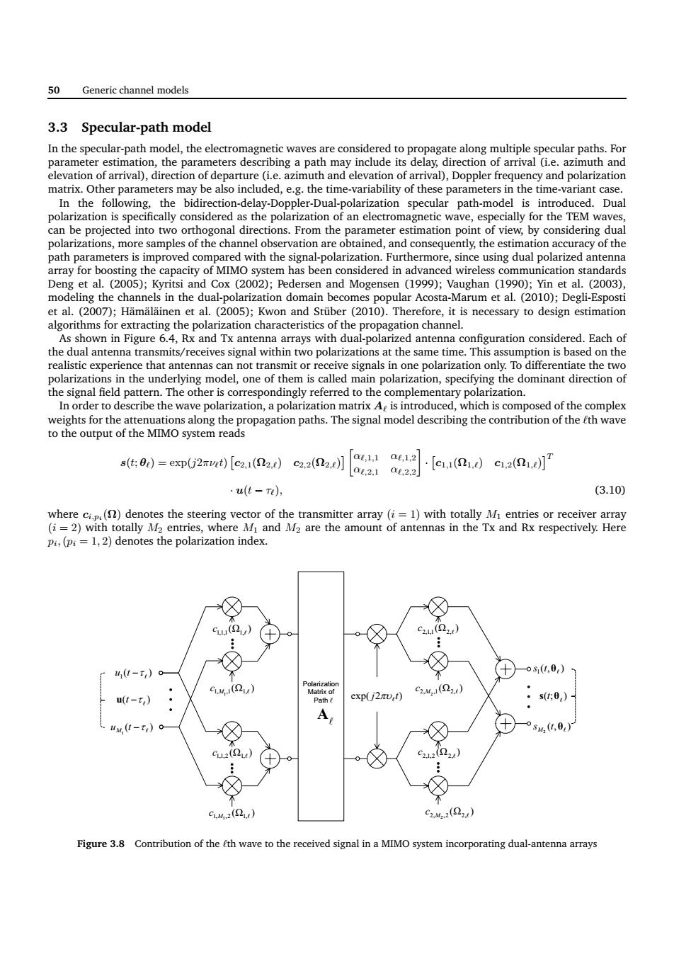
50 Generic channel models 3.3 Specular-path model az nuth and the poua the wa tua (2005):and Cox (2002)dersen and Mogense (1):Vaughan ()Yin et(003). in the on domain algorithms for extracting the polarization characteristics of the propagation channel. zed anter ennas can not transmit or receive in one polarization only To differentiate the two dominant direction of al fold on,specity wave introduced,which is composed of the com pah The model th of thehwave t=em62 c.(aa)a(a】aia-ea0)aa u(t-n) (3.10) (s)den 11 pi,(pi 1,2)denotes the polarization index. 0-)。 Q) t-) cxpj2U,t) A uv.(1-T)c Figure 3.8 Contribution of the th wave to the received signal in a MIMO system incorporating dual-antenna arrays 50 Generic channel models 3.3 Specular-path model In the specular-path model, the electromagnetic waves are considered to propagate along multiple specular paths. For parameter estimation, the parameters describing a path may include its delay, direction of arrival (i.e. azimuth and elevation of arrival), direction of departure (i.e. azimuth and elevation of arrival), Doppler frequency and polarization matrix. Other parameters may be also included, e.g. the time-variability of these parameters in the time-variant case. In the following, the bidirection-delay-Doppler-Dual-polarization specular path-model is introduced. Dual polarization is specifically considered as the polarization of an electromagnetic wave, especially for the TEM waves, can be projected into two orthogonal directions. From the parameter estimation point of view, by considering dual polarizations, more samples of the channel observation are obtained, and consequently, the estimation accuracy of the path parameters is improved compared with the signal-polarization. Furthermore, since using dual polarized antenna array for boosting the capacity of MIMO system has been considered in advanced wireless communication standards Deng et al. (2005); Kyritsi and Cox (2002); Pedersen and Mogensen (1999); Vaughan (1990); Yin et al. (2003), modeling the channels in the dual-polarization domain becomes popular Acosta-Marum et al. (2010); Degli-Esposti et al. (2007); Hämäläinen et al. (2005); Kwon and Stüber (2010). Therefore, it is necessary to design estimation algorithms for extracting the polarization characteristics of the propagation channel. As shown in Figure 6.4, Rx and Tx antenna arrays with dual-polarized antenna configuration considered. Each of the dual antenna transmits/receives signal within two polarizations at the same time. This assumption is based on the realistic experience that antennas can not transmit or receive signals in one polarization only. To differentiate the two polarizations in the underlying model, one of them is called main polarization, specifying the dominant direction of the signal field pattern. The other is correspondingly referred to the complementary polarization. In order to describe the wave polarization, a polarization matrix Aℓ is introduced, which is composed of the complex weights for the attenuations along the propagation paths. The signal model describing the contribution of the ℓth wave to the output of the MIMO system reads s(t; θℓ) = exp(j2πνℓt) c2,1(Ω2,ℓ) c2,2(Ω2,ℓ) αℓ,1,1 αℓ,1,2 αℓ,2,1 αℓ,2,2 · c1,1(Ω1,ℓ) c1,2(Ω1,ℓ) T · u(t − τℓ), (3.10) where ci,pi (Ω) denotes the steering vector of the transmitter array (i = 1) with totally M1 entries or receiver array (i = 2) with totally M2 entries, where M1 and M2 are the amount of antennas in the Tx and Rx respectively. Here pi ,(pi = 1, 2) denotes the polarization index. Polarization Matrix of Path " " A (ȍ ) ,11,1,1 " c ( ) 1 " tu W ( ) 1 " u t W M ( ) " u t W (ȍ ) 1,1,2 ,2 " c ),( 1 ș" ts );( ș" exp( j2 t) s t SX " (ȍ ) ,12,1,1 " c (ȍ ) M1 2,,1 ,1 " c ),( 2 ș" s t M (ȍ ) 2,1,2 ,2 " c (ȍ ) M1 ,11,,1 " c (ȍ ) M2 1,,2 ,2 " c (ȍ ) M2 2,,2 ,2 " c Figure 3.8 Contribution of the ℓth wave to the received signal in a MIMO system incorporating dual-antenna arrays����