正在加载图片...

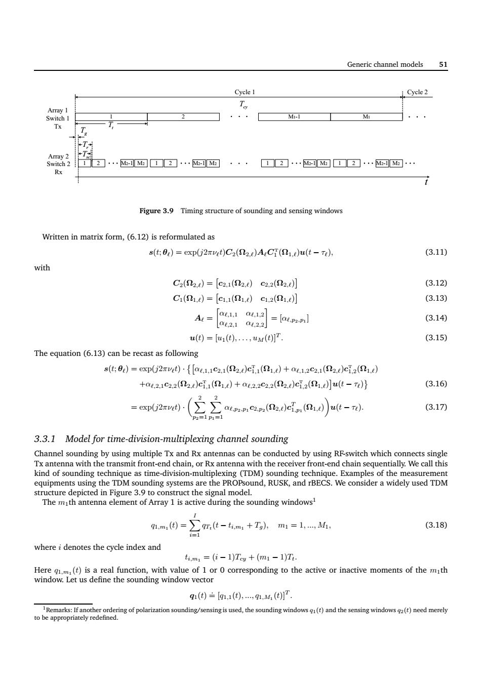
Generic channel models 51 Cyele 1 Cyele2 T 2 Mi-1 M Tx 2…网图☐2…网a··· 12.M-可M▣12·.M-可M间· Rx Figure3.9 Timing structure of sounding and sensing windows Written in matrix form,(6.12)is reformulated as s(t:0)=exp(j2rvet)C2(D2.)ACf(S)u(t-Te) (3.11) with C2(2d=[c2.12.d)c2.22.tj (3.12) C(1.0=[c,11.)c1,2(01, (3.13) =ai8a=aanl (3.14) (3.15) The equation(6.13)can be recast as following s(t0)=exp(j2rut{[ae.1c2.1(2.)cf,(1.)+a1.2c2.1(2.)cf2(1.) +a4.21c22(2.cf()+a2,2e2.2(2)ci2(1,ut-n} (3.16) (3.17刀 3.3.1 Model for time-division-multiplexing channel sounding Channel sounding can be conducted by structure depicted in Pigure 3.the signal mode The mth antenna element of Array 1 is active during the sounding windows 91,m(因=∑9m,(t-m4+Tg,m1=1,,M (3.18) whereidenotes the cycle index and t.m1=(位-1)Tw+(m1-1)T q1(④)三【m.1().,91.M( used,the soun ows()and thes )need merelyGeneric channel models 51 1 Tt 2 M1-1 M1 1 2 M2-1 M2 Cycle 1 Cycle 2 1 2 1 2 1 2 Tg Tsc Tcy t Tr Array 1 Switch 1 Tx Array 2 Switch 2 Rx M2-1 M2 M2-1 M2 M2-1 M2 Figure 3.9 Timing structure of sounding and sensing windows Written in matrix form, (6.12) is reformulated as s(t; θℓ) = exp(j2πνℓt)C2(Ω2,ℓ)AℓC T 1 (Ω1,ℓ)u(t − τℓ), (3.11) with C2(Ω2,ℓ) = c2,1(Ω2,ℓ) c2,2(Ω2,ℓ) (3.12) C1(Ω1,ℓ) = c1,1(Ω1,ℓ) c1,2(Ω1,ℓ) (3.13) Aℓ = αℓ,1,1 αℓ,1,2 αℓ,2,1 αℓ,2,2 = [αℓ,p2,p1 ] (3.14) u(t) = [u1(t), . . . , uM(t)]T . (3.15) The equation (6.13) can be recast as following s(t; θℓ) = exp(j2πνℓt) · αℓ,1,1c2,1(Ω2,ℓ)c T 1,1 (Ω1,ℓ) + αℓ,1,2c2,1(Ω2,ℓ)c T 1,2 (Ω1,ℓ) +αℓ,2,1c2,2(Ω2,ℓ)c T 1,1 (Ω1,ℓ) + αℓ,2,2c2,2(Ω2,ℓ)c T 1,2 (Ω1,ℓ) u(t − τℓ) (3.16) = exp(j2πνℓt) · X 2 p2=1 X 2 p1=1 αℓ,p2,p1 c2,p2 (Ω2,ℓ)c T 1,p1 (Ω1,ℓ) u(t − τℓ). (3.17) 3.3.1 Model for time-division-multiplexing channel sounding Channel sounding by using multiple Tx and Rx antennas can be conducted by using RF-switch which connects single Tx antenna with the transmit front-end chain, or Rx antenna with the receiver front-end chain sequentially. We call this kind of sounding technique as time-division-multiplexing (TDM) sounding technique. Examples of the measurement equipments using the TDM sounding systems are the PROPsound, RUSK, and rBECS. We consider a widely used TDM structure depicted in Figure 3.9 to construct the signal model. The m1th antenna element of Array 1 is active during the sounding windows1 q1,m1 (t) = X I i=1 qTt (t − ti,m1 + Tg), m1 = 1, ..., M1, (3.18) where i denotes the cycle index and ti,m1 = (i − 1)Tcy + (m1 − 1)Tt. Here q1,m1 (t) is a real function, with value of 1 or 0 corresponding to the active or inactive moments of the m1th window. Let us define the sounding window vector q1(t) .= [q1,1(t), ..., q1,M1 (t)]T . 1Remarks: If another ordering of polarization sounding/sensing is used, the sounding windows q1(t) and the sensing windows q2(t) need merely to be appropriately redefined.������