正在加载图片...
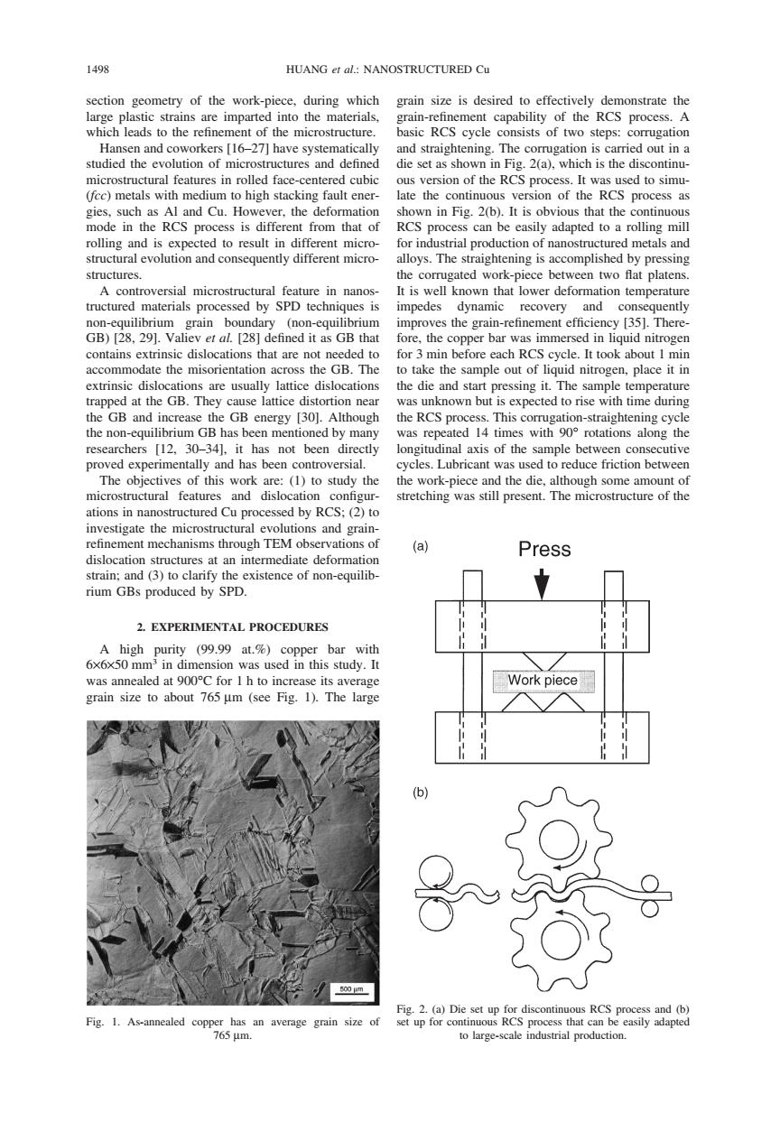
1498 HUANG et al:NANOSTRUCTURED Cu section geometry of the work-piece,during which grain size is desired to effectively demonstrate the large plastic strains are imparted into the materials, grain-refinement capability of the RCS process.A which leads to the refinement of the microstructure. basic RCS cycle consists of two steps:corrugation Hansen and coworkers [16-27]have systematically and straightening.The corrugation is carried out in a studied the evolution of microstructures and defined die set as shown in Fig.2(a),which is the discontinu- microstructural features in rolled face-centered cubic ous version of the RCS process.It was used to simu- (fcc)metals with medium to high stacking fault ener- late the continuous version of the RCS process as gies,such as Al and Cu.However,the deformation shown in Fig.2(b).It is obvious that the continuous mode in the RCS process is different from that of RCS process can be easily adapted to a rolling mill rolling and is expected to result in different micro- for industrial production of nanostructured metals and structural evolution and consequently different micro- alloys.The straightening is accomplished by pressing structures. the corrugated work-piece between two flat platens. A controversial microstructural feature in nanos- It is well known that lower deformation temperature tructured materials processed by SPD techniques is impedes dynamic recovery and consequently non-equilibrium grain boundary (non-equilibrium improves the grain-refinement efficiency [35].There- GB)[28,29].Valiev et al.[28]defined it as GB that fore,the copper bar was immersed in liquid nitrogen contains extrinsic dislocations that are not needed to for 3 min before each RCS cycle.It took about 1 min accommodate the misorientation across the GB.The to take the sample out of liquid nitrogen,place it in extrinsic dislocations are usually lattice dislocations the die and start pressing it.The sample temperature trapped at the GB.They cause lattice distortion near was unknown but is expected to rise with time during the GB and increase the GB energy [30].Although the RCS process.This corrugation-straightening cycle the non-equilibrium GB has been mentioned by many was repeated 14 times with 90 rotations along the researchers [12,30-34],it has not been directly longitudinal axis of the sample between consecutive proved experimentally and has been controversial. cycles.Lubricant was used to reduce friction between The objectives of this work are:(1)to study the the work-piece and the die,although some amount of microstructural features and dislocation configur- stretching was still present.The microstructure of the ations in nanostructured Cu processed by RCS:(2)to investigate the microstructural evolutions and grain- refinement mechanisms through TEM observations of (a) Press dislocation structures at an intermediate deformation strain;and (3)to clarify the existence of non-equilib- rium GBs produced by SPD. 2.EXPERIMENTAL PROCEDURES A high purity (99.99 at.%)copper bar with 6x6x50 mm3 in dimension was used in this study.It was annealed at 900C for I h to increase its average Work piece grain size to about 765 um (see Fig.1).The large (b) 500m Fig.2.(a)Die set up for discontinuous RCS process and (b) Fig.1.As-annealed copper has an average grain size of set up for continuous RCS process that can be easily adapted 765μm. to large-scale industrial production.1498 HUANG et al.: NANOSTRUCTURED Cu section geometry of the work-piece, during which large plastic strains are imparted into the materials, which leads to the refinement of the microstructure. Hansen and coworkers [16–27] have systematically studied the evolution of microstructures and defined microstructural features in rolled face-centered cubic (fcc) metals with medium to high stacking fault energies, such as Al and Cu. However, the deformation mode in the RCS process is different from that of rolling and is expected to result in different microstructural evolution and consequently different microstructures. A controversial microstructural feature in nanostructured materials processed by SPD techniques is non-equilibrium grain boundary (non-equilibrium GB) [28, 29]. Valiev et al. [28] defined it as GB that contains extrinsic dislocations that are not needed to accommodate the misorientation across the GB. The extrinsic dislocations are usually lattice dislocations trapped at the GB. They cause lattice distortion near the GB and increase the GB energy [30]. Although the non-equilibrium GB has been mentioned by many researchers [12, 30–34], it has not been directly proved experimentally and has been controversial. The objectives of this work are: (1) to study the microstructural features and dislocation configurations in nanostructured Cu processed by RCS; (2) to investigate the microstructural evolutions and grainrefinement mechanisms through TEM observations of dislocation structures at an intermediate deformation strain; and (3) to clarify the existence of non-equilibrium GBs produced by SPD. 2. EXPERIMENTAL PROCEDURES A high purity (99.99 at.%) copper bar with 6×6×50 mm3 in dimension was used in this study. It was annealed at 900°C for 1 h to increase its average grain size to about 765 µm (see Fig. 1). The large Fig. 1. As-annealed copper has an average grain size of 765 µm. grain size is desired to effectively demonstrate the grain-refinement capability of the RCS process. A basic RCS cycle consists of two steps: corrugation and straightening. The corrugation is carried out in a die set as shown in Fig. 2(a), which is the discontinuous version of the RCS process. It was used to simulate the continuous version of the RCS process as shown in Fig. 2(b). It is obvious that the continuous RCS process can be easily adapted to a rolling mill for industrial production of nanostructured metals and alloys. The straightening is accomplished by pressing the corrugated work-piece between two flat platens. It is well known that lower deformation temperature impedes dynamic recovery and consequently improves the grain-refinement efficiency [35]. Therefore, the copper bar was immersed in liquid nitrogen for 3 min before each RCS cycle. It took about 1 min to take the sample out of liquid nitrogen, place it in the die and start pressing it. The sample temperature was unknown but is expected to rise with time during the RCS process. This corrugation-straightening cycle was repeated 14 times with 90° rotations along the longitudinal axis of the sample between consecutive cycles. Lubricant was used to reduce friction between the work-piece and the die, although some amount of stretching was still present. The microstructure of the Fig. 2. (a) Die set up for discontinuous RCS process and (b) set up for continuous RCS process that can be easily adapted to large-scale industrial production