正在加载图片...
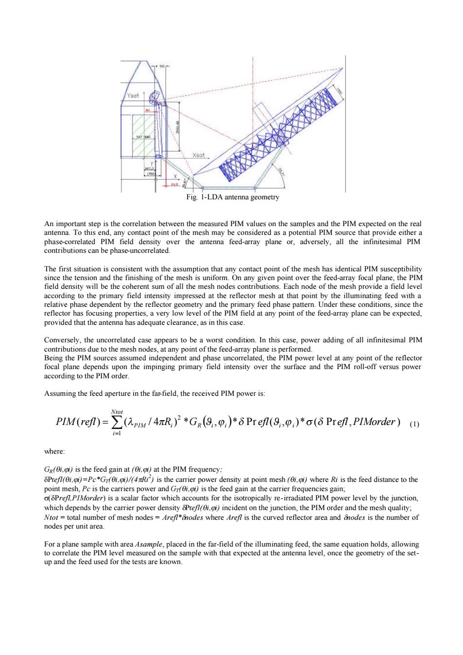
Fig I-LDA antenn An imporant step is the correlation betwe n the measured PIM values on the samples and the PIM expected on the real antenna To this contrnibutionscanbcphase-lncorclatedWver ay p or.adversely. identical PIM d-array focal int by provided that the nte hasadequatecrance.nae Conversely.the uncorrelated case appears to be a worst condition.In this case.power adding of all infinitesimal PIM level a according to the PIM orde Assuming the feed aperture in the farfield,the received PIM power is: PMef=∑(apwI4R2*Gn(9,o,)*δPref9,p,)*a(6Pren,PIMorder)四 where gi-PetG /0i density at point Ri is the feed distance to the point mesh,Peis the carriers power and Gis the feed gain at the gain, er)is a scala y re-iradlate Nor=total number of mesh nodes-rede where reis the curved reflector area and ode is thenumber of nodes per unit area. up and the feed used for the tests are known.Fig. 1-LDA antenna geometry An important step is the correlation between the measured PIM values on the samples and the PIM expected on the real antenna. To this end, any contact point of the mesh may be considered as a potential PIM source that provide either a phase-correlated PIM field density over the antenna feed-array plane or, adversely, all the infinitesimal PIM contributions can be phase-uncorrelated. The first situation is consistent with the assumption that any contact point of the mesh has identical PIM susceptibility since the tension and the finishing of the mesh is uniform. On any given point over the feed-array focal plane, the PIM field density will be the coherent sum of all the mesh nodes contributions. Each node of the mesh provide a field level according to the primary field intensity impressed at the reflector mesh at that point by the illuminating feed with a relative phase dependent by the reflector geometry and the primary feed phase pattern. Under these conditions, since the reflector has focusing properties, a very low level of the PIM field at any point of the feed-array plane can be expected, provided that the antenna has adequate clearance, as in this case. Conversely, the uncorrelated case appears to be a worst condition. In this case, power adding of all infinitesimal PIM contributions due to the mesh nodes, at any point of the feed-array plane is performed. Being the PIM sources assumed independent and phase uncorrelated, the PIM power level at any point of the reflector focal plane depends upon the impinging primary field intensity over the surface and the PIM roll-off versus power according to the PIM order. Assuming the feed aperture in the far-field, the received PIM power is: ( ) ( / 4 ) * ( , )* Pr ( , )* ( Pr , ) 1 2 PIM refl R G efl efl PIMorder i i Ntot i å lPIM p i R Ji ji d J j s d = = (1) where: GR(qi,ji) is the feed gain at (qi,ji) at the PIM frequency; dPrefl(qi,ji)=Pc*GT(qi,ji)/(4pRi2 ) is the carrier power density at point mesh (qi,ji) where Ri is the feed distance to the point mesh, Pc is the carriers power and GT(qi,ji) is the feed gain at the carrier frequencies gain; s(dPrefl,PIMorder) is a scalar factor which accounts for the isotropically re-irradiated PIM power level by the junction, which depends by the carrier power density dPrefl(qi,ji) incident on the junction, the PIM order and the mesh quality; Ntot = total number of mesh nodes = Arefl*dnodes where Arefl is the curved reflector area and dnodes is the number of nodes per unit area. For a plane sample with area Asample, placed in the far-field of the illuminating feed, the same equation holds, allowing to correlate the PIM level measured on the sample with that expected at the antenna level, once the geometry of the setup and the feed used for the tests are known