正在加载图片...
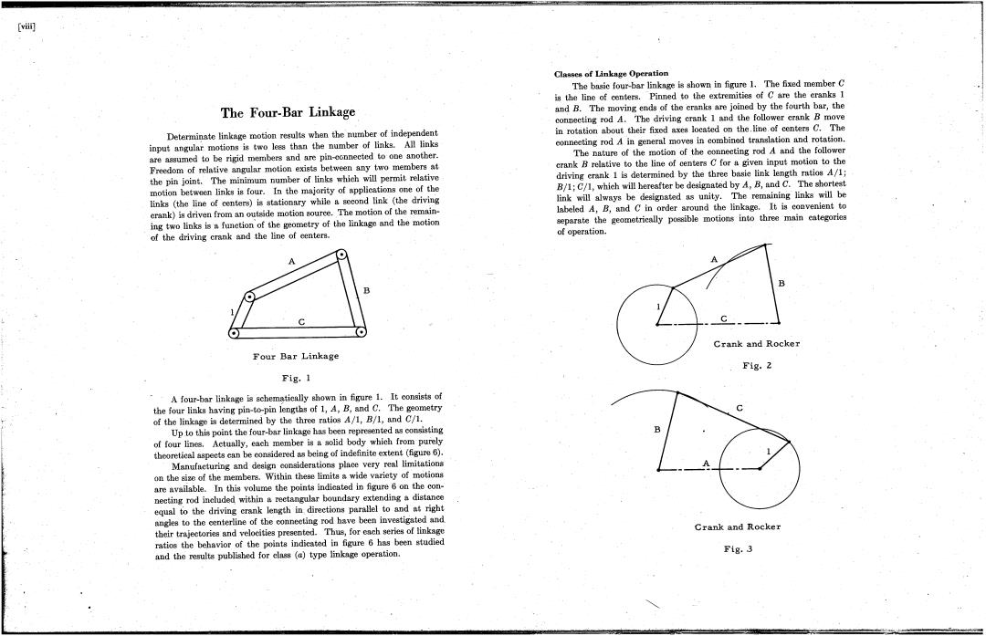
[vii] Classes of Linkage Operation The basie four-bar linknge is shown in figure 1.The fixed member C is the line of centers.Pinned to the extremities of C are the eranks I The Four-Bar Linkage and B.The moving ends of the cranks are joined by the fourth bar,the connecting rod A.The driving crank 1 and the follower crank B move Determinate linkage motion results when the number of independent in rotation about their fixod axes located on the.line.of centers C.The input angular motions is two less than the number of links.All links conneeting rod A in general moves in combined translation and rotation. are assumed to be rigid members and are pin-eonnected to one another. The nature of the motion of the connecting rod A and the follower Freedom of relative angular motion exists between any two members at crank B relative to the line of eenters C for a given input motion to the the pin joint.The minimum number of links which will permit relative driving crank 1 is determined by the three basie link length ratios A/1; motion between links is four.In the majority of applications one of the B/1:C/1,which will hereafter be designated by A,B,and C.The shortest links (the line of centers)is stationary while a second link (the driving link will always be designated as unity.The remaining links will be erank)is driven from an outside motion source.The motion of the remnin- labeled A,B,and C in order around the linkage.It is convenient to ing two links is a funetion of the geometry of the linkage and the motion separate the geometrically poesible motions into three main eategories of the driving crank and the line of eenters. of operation. A C Crank and Rocker Four Bar Linkage F1g.2 Fig.1 A four-bar linkage is schematieally shown in figure 1.It oonsists of the four links having pin-to-pin lengths of 1,A,B,and C.The geometry of the linkage is determined by the three ratios A/1,B/1,and C/1. Up to this point the four-bar linkage has been represented as consisting of four lines.Actually,each member is a solid body which from purely theoretical aspects can be considered as being of indefinite extent (figure 6). Manufacturing and design considerations place very real limitationa on the size of the membera.Within these limits a wide variety of motions are available.In this volume the points indicated in figure 6 on the con- necting rod included within a reetangular boundary extending a distance equal to the driving crank length in directions parallel to and at right angles to the centerline of the conneeting rod have been inveatigated and their trajeetories and velocities presented.Thus,for each series of linkago Crank and Rocker ratios the behavior of the points indicated in figure 6 has been studied and the results publisbed for ls(a)type linkage operation. F1g.3( viiiJ The F our- Bar Linkage Classes of Linkage Operation The basic four-bar linkage is shown in figure 1. The fixed member is the line of centers. . Pinned to the extremities of are the cranks 1 and B. The moving ends of the cranks are joined by the fourth bar, the coIWecting rod A. The driving crank 1 "and the follower crank move in rotation about their fixed axes located on the .line of centers G. The connecting rod in general moves jn combined translation and rotation. The nature of the motion of the conhecting rod and the follower crank relative to the line of centers fora given input motion to the driving crank 1 is determined by the three basic link length ratios All; BIl; Gl1 which will hereaJterbe designated by , B and G. The shortest link will always be designated as unity, The remaining links will be labeled , B ahd in order around the linkage. It is convenient to separate the geometrically possible motions into three main categories of operation. Determi~ate linkage motion results when the number of independent input angular motions is two less than the number of links, All links are assumed to be rigid members and are pin-connected to one another. Freedom of relative angular motion exists between any two members at the pin joint. The minimum number of links which will permit relative motion between links is four. In the majority of applications one of the links (the line of centers) is stationary while a second link (the driving crank) is driven from an outside motion source. The motion of the remain- ' . ing two links isa function of the geometry of the linkage and the motion of the driving crank and the line of centers. Crank and Rocke Four Bar Linkage Fig. 2 Fig. 1 A four-bar linkage isschema.tically shown in figure 1. It consists of the four links having pin-to-pin lengths of 1 , B and G. The geometry of the linkage is determined by the three ratios All, Bl1 and GI1. Up ,to this point the four-bar linkage has been represented as consisting of four lines, Actually, each member is a solid body which from purely theoretical aspects can be considered as being of indefinite extent (figure 6). Manufacturing and design considerations place very real limitations on the size of the members. Within these limits a wide variety of motions are available. In this volume the points indicated in figure 6 on the connecting rod included.. within a rectangular boundary extending a distance equal to the driving crank length in directions parallel to and at right angles to the centerline of the connecting rod have been investigated and, their trajectories and velocities presented, Thus, for each series of linkage ratios the behavior of the points indicated in figure 6 has been studied and the results published for class (a) type linkage operation. Crank and Rocker Fig. 3 -..,,- ~c-'" " "",' T..- ~"'--