正在加载图片...
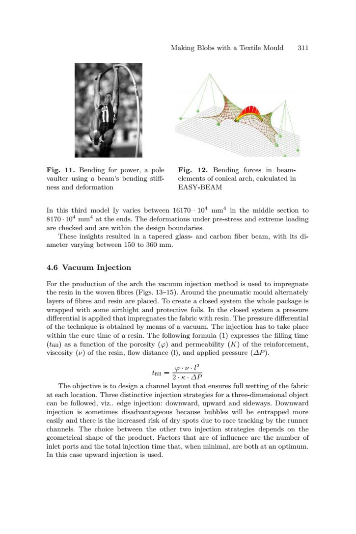
Making Blobs with a Textile Mould 311 Fig.11.Bending for power,a pole Fig.12.Bending forces in beam- vaulter using a beam's bending stiff- elements of conical arch.calculated in ness and deformation EASY-BEAM In this third model Iy varies between 16170.104 mm4 in the middle section to 8170.104 mm at the ends.The deformations under pre-stress and extreme loading are checked and are within the design boundaries. These insights resulted in a tapered glass-and carbon fiber beam,with its di- ameter varying between 150 to 360 mm. 4.6 Vacuum Injection For the production of the arch the vacuum injection method is used to impregnate the resin in the woven fibres (Figs.13-15).Around the pneumatic mould alternately layers of fibres and resin are placed.To create a closed system the whole package is wrapped with some airthight and protective foils.In the closed system a pressure differential is applied that impregnates the fabric with resin.The pressure differential of the technique is obtained by means of a vacuum.The injection has to take place within the cure time of a resin.The following formula (1)expresses the filling time (tan)as a function of the porosity (and permeability (K)of the reinforcement, viscosity ()of the resin,flow distance (1),and applied pressure (AP). 品 The objective is to design a channel layout that ensures full wetting of the fabric at each location.Three distinctive injection strategies for a three-dimensional object can be followed,viz..edge injection:downward,upward and sideways.Downward injection is sometimes disadvantageous because bubbles will be entrapped more easily and there is the increased risk of dry spots due to race tracking by the runner channels.The choice between the other two injection strategies depends on the geometrical shape of the product.Factors that are of influence are the number of inlet ports and the total injection time that,when minimal,are both at an optimum. In this case upward injection is used.Making Blobs with a Textile Mould 311 Fig. 11. Bending for power, a pole vaulter using a beam’s bending stiff- ness and deformation Fig. 12. Bending forces in beamelements of conical arch, calculated in EASY-BEAM In this third model Iy varies between 16170 · 104 mm4 in the middle section to 8170 · 104 mm4 at the ends. The deformations under pre-stress and extreme loading are checked and are within the design boundaries. These insights resulted in a tapered glass- and carbon fiber beam, with its diameter varying between 150 to 360 mm. 4.6 Vacuum Injection For the production of the arch the vacuum injection method is used to impregnate the resin in the woven fibres (Figs. 13–15). Around the pneumatic mould alternately layers of fibres and resin are placed. To create a closed system the whole package is wrapped with some airthight and protective foils. In the closed system a pressure differential is applied that impregnates the fabric with resin. The pressure differential of the technique is obtained by means of a vacuum. The injection has to take place within the cure time of a resin. The following formula (1) expresses the filling time (tfill) as a function of the porosity (ϕ) and permeability (K) of the reinforcement, viscosity (ν) of the resin, flow distance (l), and applied pressure (∆P). tfill = ϕ · ν · l 2 2 · κ · ∆P The objective is to design a channel layout that ensures full wetting of the fabric at each location. Three distinctive injection strategies for a three-dimensional object can be followed, viz.. edge injection: downward, upward and sideways. Downward injection is sometimes disadvantageous because bubbles will be entrapped more easily and there is the increased risk of dry spots due to race tracking by the runner channels. The choice between the other two injection strategies depends on the geometrical shape of the product. Factors that are of influence are the number of inlet ports and the total injection time that, when minimal, are both at an optimum. In this case upward injection is used