正在加载图片...

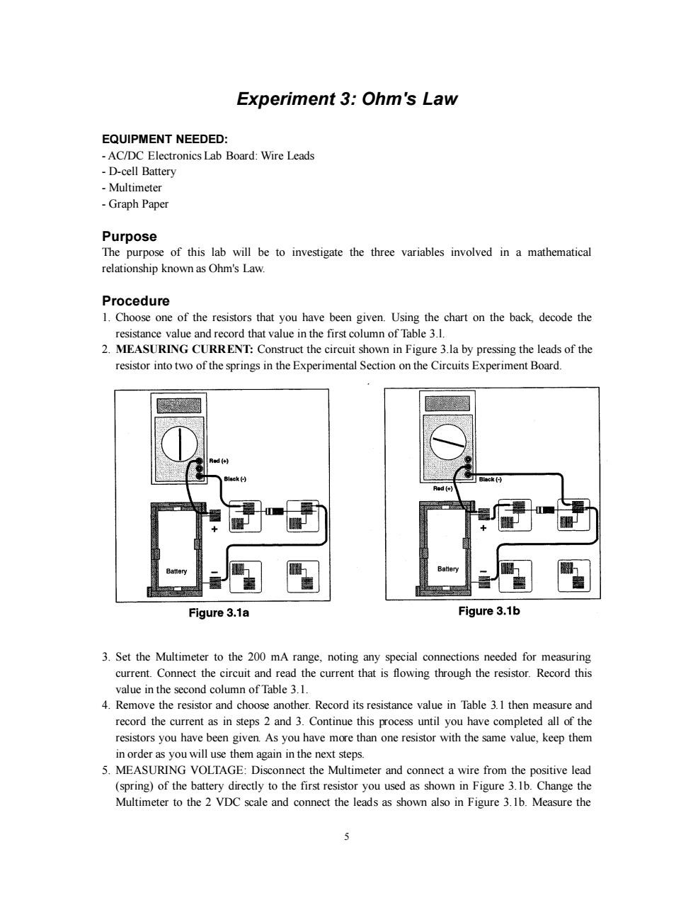
Experiment 3:Ohm's Law EQUIPMENT NEEDED: -AC/DC Electronics Lab Board:Wire Leads -D-cell Battery Multimeter -Graph Paper Purpose The purpose of this lab will be to investigate the three variables involved in a mathematical relationship known as Ohm's Law. Procedure 1.Choose one of the resistors that you have been given.Using the chart on the back,decode the resistance value and record that value in the first column of Table 3.1. 2.MEASURING CURRENT:Construct the circuit shown in Figure 3.la by pressing the leads of the resistor into two of the springs in the Experimental Section on the Circuits Experiment Board. Black(-) B墙ck(H Red (+ Battery Figure 3.1a Figure 3.1b 3.Set the Multimeter to the 200 mA range,noting any special connections needed for measuring current.Connect the circuit and read the current that is flowing through the resistor.Record this value in the second column of Table 3.1. 4.Remove the resistor and choose another.Record its resistance value in Table 3.1 then measure and record the current as in steps 2 and 3.Continue this process until you have completed all of the resistors you have been given.As you have more than one resistor with the same value,keep them in order as you will use them again in the next steps. 5.MEASURING VOLTAGE:Disconnect the Multimeter and connect a wire from the positive lead (spring)of the battery directly to the first resistor you used as shown in Figure 3.1b.Change the Multimeter to the 2 VDC scale and connect the leads as shown also in Figure 3.1b.Measure the 55 Experiment 3: Ohm's Law EQUIPMENT NEEDED: - AC/DC Electronics Lab Board: Wire Leads - D-cell Battery - Multimeter - Graph Paper Purpose The purpose of this lab will be to investigate the three variables involved in a mathematical relationship known as Ohm's Law. Procedure 1. Choose one of the resistors that you have been given. Using the chart on the back, decode the resistance value and record that value in the first column of Table 3.l. 2. MEASURING CURRENT: Construct the circuit shown in Figure 3.la by pressing the leads of the resistor into two of the springs in the Experimental Section on the Circuits Experiment Board. 3. Set the Multimeter to the 200 mA range, noting any special connections needed for measuring current. Connect the circuit and read the current that is flowing through the resistor. Record this value in the second column of Table 3.1. 4. Remove the resistor and choose another. Record its resistance value in Table 3.1 then measure and record the current as in steps 2 and 3. Continue this process until you have completed all of the resistors you have been given. As you have more than one resistor with the same value, keep them in order as you will use them again in the next steps. 5. MEASURING VOLTAGE: Disconnect the Multimeter and connect a wire from the positive lead (spring) of the battery directly to the first resistor you used as shown in Figure 3.1b. Change the Multimeter to the 2 VDC scale and connect the leads as shown also in Figure 3.1b. Measure the