正在加载图片...
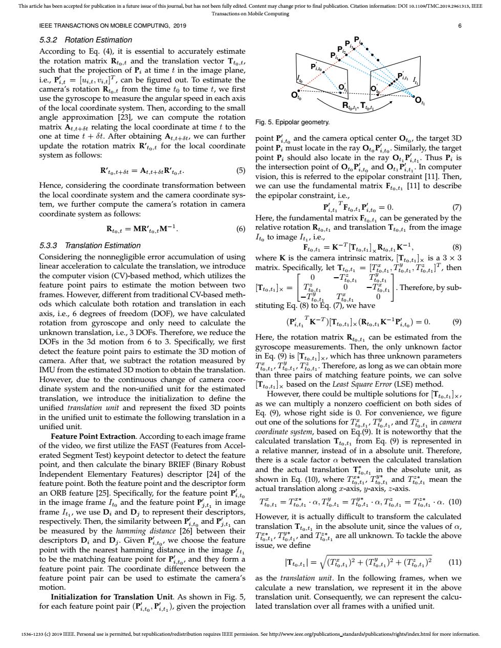
This article has been accepted for publication in a future issue of this journal,but has not been fully edited.Content may change prior to final publication.Citation information:DOI 10.1109/TMC.2019.2961313.IEEE Transactions on Mobile Computing IEEE TRANSACTIONS ON MOBILE COMPUTING,2019 5.3.2 Rotation Estimation P According to Eg.(4),it is essential to accurately estimate the rotation matrix Rto.t and the translation vector Tto.t, P such that the projection of Pi at time t in the image plane, i.e.,Pi.t =[ui.t,vi.t,can be figured out.To estimate the camera's rotation Rto.t from the time to to time t,we first ● use the gyroscope to measure the angular speed in each axis of the local coordinate system.Then,according to the small angle approximation [23],we can compute the rotation Fig.5.Epipolar geometry. matrix At.t+6t relating the local coordinate at time t to the one at time t+6t.After obtaining At.t+t,we can further point Pt and the camera optical center Oto the target 3D update the rotation matrix R'to.t for the local coordinate point Pi must locate in the ray OtoPtSimilarly,the target system as follows: point Pi should also locate in the ray Ot P Thus Pi is R'to.t+8t=At.t+5tR'to.t. (5) the intersection point of OtoPi.to and O Pi.tIn computer vision,this is referred to the epipolar constraint [11].Then, Hence,considering the coordinate transformation between we can use the fundamental matrix Fto.t [11]to describe the local coordinate system and the camera coordinate sys- the epipolar constraint,i.e., tem,we further compute the camera's rotation in camera PiFo Pto=0. ( coordinate system as follows: Here,the fundamental matrix Fto.t can be generated by the Rto.t MR'to.M-1 (6) relative rotation Rto.t and translation Tto.t from the image Ito to image It,i.e., 5.3.3 Translation Estimation Fto=K-T[Tto.]RtoK-1, (8) Considering the nonnegligible error accumulation of using where K is the camera intrinsic matrix,[Tto.tlx is a 3 x 3 linear acceleration to calculate the translation,we introduce matrix.Specifically,let To=[TTT,then the computer vision(CV)-based method,which utilizes the 0 T ,ti feature point pairs to estimate the motion between two [Tto,t]×= frames.However,different from traditional CV-based meth- To Tio.ti 0 -1tot Therefore,by sub- to,t1 ods which calculate both rotation and translation in each Ttot 0 stituting Eq.(8)to Eq.(7),we have axis,i.e.,6 degrees of freedom (DOF),we have calculated rotation from gyroscope and only need to calculate the (PK-T)[Tx(RK-Pit)=0. (9) unknown translation,i.e.,3 DOFs.Therefore,we reduce the DOFs in the 3d motion from 6 to 3.Specifically,we first Here,the rotation matrix Rto.t can be estimated from the detect the feature point pairs to estimate the 3D motion of gyroscope measurements.Then,the only unknown factor camera.After that,we subtract the rotation measured by in Eq.(9)is [Tto.t]x,which has three unknown parameters IMU from the estimated 3D motion to obtain the translation. TTTTherefore,as long as we can obtain more However,due to the continuous change of camera coor- than three pairs of matching feature points,we can solve dinate system and the non-unified unit for the estimated Tto.]x based on the Least Square Error (LSE)method. translation,we introduce the initialization to define the However,there could be multiple solutions for [Tto.x, unified translation unit and represent the fixed 3D points as we can multiply a nonzero coefficient on both sides of in the unified unit to estimate the following translation in a Eq.(9),whose right side is 0.For convenience,we figure unified unit. out one of the solutions for TTand Tin camera Feature Point Extraction.According to each image frame coordinate system,based on Eq.(9).It is noteworthy that the of the video,we first utilize the FAST(Features from Accel- calculated translation Tto.t from Eq.(9)is represented in a relative manner,instead of in a absolute unit.Therefore, erated Segment Test)keypoint detector to detect the feature point,and then calculate the binary BRIEF(Binary Robust there is a scale factor a between the calculated translation Independent Elementary Features)descriptor [24]of the and the actual translation Tin the absolute unit,as feature point.Both the feature point and the descriptor form shown in Eq.(10),where TT and T mean the an ORB feature [25].Specifically,for the feature point Pito actual translation along x-axis,y-axis,z-axis. in the image frame Ito and the feature point Pt in image T0t=T1a,T%=T%1·a,T01=T0a.(0) frame It,we use Di and Di to represent their descriptors, respectively.Then,the similarity between Pand P However,it is actually difficult to transform the calculated can be measured by the hamming distance [26]between their translation Tto.t in the absolute unit,since the values of o, descriptors Di and Di.Given Pito we choose the feature TTand T are all unknown.To tackle the above issue,we define point with the nearest hamming distance in the image It to be the matching feature point for Pi.to and they form a Tto.t=V(To.t)2+(T)2+(T)2 (11) feature point pair.The coordinate difference between the feature point pair can be used to estimate the camera's as the translation unit.In the following frames,when we motion. calculate a new translation,we represent it in the above Initialization for Translation Unit.As shown in Fig.5, translation unit.Consequently,we can represent the calcu- for each feature point pair(Pi.to Pit),given the projection lated translation over all frames with a unified unit. 1536-1233 (c)2019 IEEE Personal use is permitted,but republication/redistribution requires IEEE permission.See http://www.ieee.org/publications_standards/publications/rights/index.html for more information.1536-1233 (c) 2019 IEEE. Personal use is permitted, but republication/redistribution requires IEEE permission. See http://www.ieee.org/publications_standards/publications/rights/index.html for more information. This article has been accepted for publication in a future issue of this journal, but has not been fully edited. Content may change prior to final publication. Citation information: DOI 10.1109/TMC.2019.2961313, IEEE Transactions on Mobile Computing IEEE TRANSACTIONS ON MOBILE COMPUTING, 2019 6 5.3.2 Rotation Estimation According to Eq. (4), it is essential to accurately estimate the rotation matrix Rt0,t and the translation vector Tt0,t, such that the projection of Pi at time t in the image plane, i.e., P 0 i,t = [ui,t, vi,t] T , can be figured out. To estimate the camera’s rotation Rt0,t from the time t0 to time t, we first use the gyroscope to measure the angular speed in each axis of the local coordinate system. Then, according to the small angle approximation [23], we can compute the rotation matrix At,t+δt relating the local coordinate at time t to the one at time t + δt. After obtaining At,t+δt, we can further update the rotation matrix R’t0,t for the local coordinate system as follows: R’t0,t+δt = At,t+δtR’t0,t. (5) Hence, considering the coordinate transformation between the local coordinate system and the camera coordinate system, we further compute the camera’s rotation in camera coordinate system as follows: Rt0,t = MR’t0,tM−1 . (6) 5.3.3 Translation Estimation Considering the nonnegligible error accumulation of using linear acceleration to calculate the translation, we introduce the computer vision (CV)-based method, which utilizes the feature point pairs to estimate the motion between two frames. However, different from traditional CV-based methods which calculate both rotation and translation in each axis, i.e., 6 degrees of freedom (DOF), we have calculated rotation from gyroscope and only need to calculate the unknown translation, i.e., 3 DOFs. Therefore, we reduce the DOFs in the 3d motion from 6 to 3. Specifically, we first detect the feature point pairs to estimate the 3D motion of camera. After that, we subtract the rotation measured by IMU from the estimated 3D motion to obtain the translation. However, due to the continuous change of camera coordinate system and the non-unified unit for the estimated translation, we introduce the initialization to define the unified translation unit and represent the fixed 3D points in the unified unit to estimate the following translation in a unified unit. Feature Point Extraction. According to each image frame of the video, we first utilize the FAST (Features from Accelerated Segment Test) keypoint detector to detect the feature point, and then calculate the binary BRIEF (Binary Robust Independent Elementary Features) descriptor [24] of the feature point. Both the feature point and the descriptor form an ORB feature [25]. Specifically, for the feature point P 0 i,t0 in the image frame It0 and the feature point P 0 j,t1 in image frame It1 , we use Di and Dj to represent their descriptors, respectively. Then, the similarity between P 0 i,t0 and P 0 j,t1 can be measured by the hamming distance [26] between their descriptors Di and Dj . Given P 0 i,t0 , we choose the feature point with the nearest hamming distance in the image It1 to be the matching feature point for P 0 i,t0 , and they form a feature point pair. The coordinate difference between the feature point pair can be used to estimate the camera’s motion. Initialization for Translation Unit. As shown in Fig. 5, for each feature point pair (P 0 i,t0 , P 0 i,t1 ), given the projection Ot0 Ot R 1 t0,t1 , Tt0,t1 It0 It1 P ′ i,t0 P ′ i,t1 O ′ t0 Pi1 Pi2 Pi3 Pi O ′ t1 Fig. 5. Epipolar geometry. point P 0 i,t0 and the camera optical center Ot0 , the target 3D point Pi must locate in the ray Ot0 P 0 i,t0 . Similarly, the target point Pi should also locate in the ray Ot1 P 0 i,t1 . Thus Pi is the intersection point of Ot0 P 0 i,t0 and Ot1 P 0 i,t1 . In computer vision, this is referred to the epipolar constraint [11]. Then, we can use the fundamental matrix Ft0,t1 [11] to describe the epipolar constraint, i.e., P 0 i,t1 T Ft0,t1 P 0 i,t0 = 0. (7) Here, the fundamental matrix Ft0,t1 can be generated by the relative rotation Rt0,t1 and translation Tt0,t1 from the image It0 to image It1 , i.e., Ft0,t1 = K −T [Tt0,t1 ]×Rt0,t1K −1 , (8) where K is the camera intrinsic matrix, [Tt0,t1 ]× is a 3 × 3 matrix. Specifically, let Tt0,t1 = [T x t0,t1 , Ty t0,t1 , Tz t0,t1 ] T , then [Tt0,t1 ]× = 0 −T z t0,t1 T y t0,t1 T z t0,t1 0 −T x t0,t1 −T y t0,t1 T x t0,t1 0 . Therefore, by substituting Eq. (8) to Eq. (7), we have (P 0 i,t1 T K −T )[Tt0,t1 ]×(Rt0,t1K −1P 0 i,t0 ) = 0. (9) Here, the rotation matrix Rt0,t1 can be estimated from the gyroscope measurements. Then, the only unknown factor in Eq. (9) is [Tt0,t1 ]×, which has three unknown parameters T x t0,t1 , T y t0,t1 , T z t0,t1 . Therefore, as long as we can obtain more than three pairs of matching feature points, we can solve [Tt0,t1 ]× based on the Least Square Error (LSE) method. However, there could be multiple solutions for [Tt0,t1 ]×, as we can multiply a nonzero coefficient on both sides of Eq. (9), whose right side is 0. For convenience, we figure out one of the solutions for T x t0,t1 , T y t0,t1 , and T z t0,t1 in camera coordinate system, based on Eq.(9). It is noteworthy that the calculated translation Tt0,t1 from Eq. (9) is represented in a relative manner, instead of in a absolute unit. Therefore, there is a scale factor α between the calculated translation and the actual translation T ∗ t0,t1 in the absolute unit, as shown in Eq. (10), where T x∗ t0,t1 , T y∗ t0,t1 and T z∗ t0,t1 mean the actual translation along x-axis, y-axis, z-axis. T x t0,t1 = T x∗ t0,t1 · α, Ty t0,t1 = T y∗ t0,t1 · α, Tz t0,t1 = T z∗ t0,t1 · α. (10) However, it is actually difficult to transform the calculated translation Tt0,t1 in the absolute unit, since the values of α, T x∗ t0,t1 , T y∗ t0,t1 , and T z∗ t0,t1 are all unknown. To tackle the above issue, we define |Tt0,t1 | = q (T x t0,t1 ) 2 + (T y t0,t1 ) 2 + (T z t0,t1 ) 2 (11) as the translation unit. In the following frames, when we calculate a new translation, we represent it in the above translation unit. Consequently, we can represent the calculated translation over all frames with a unified unit