正在加载图片...
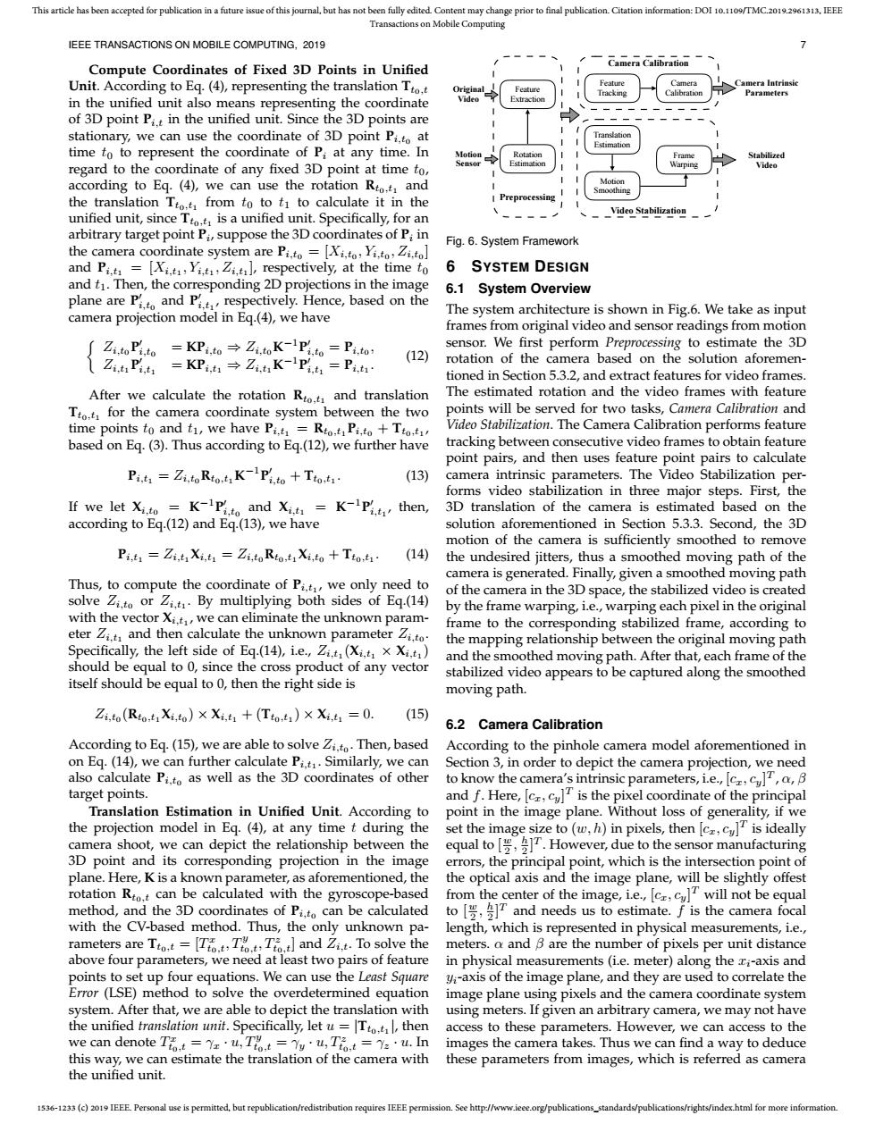
This article has been accepted for publication in a future issue of this journal,but has not been fully edited.Content may change prior to final publication.Citation information:DOI 10.1109/TMC.2019.2961313.IEEE Transactions on Mobile Computing IEEE TRANSACTIONS ON MOBILE COMPUTING,2019 Camera Calibration Compute Coordinates of Fixed 3D Points in Unified Unit.According to Eq.(4),representing the translation Tto.t in the unified unit also means representing the coordinate of 3D point Pit in the unified unit.Since the 3D points are stationary,we can use the coordinate of 3D point Pi.to at time to to represent the coordinate of P:at any time.In regard to the coordinate of any fixed 3D point at time to, according to Eq.(4),we can use the rotation Rto.t and the translation Tto.t from to to ti to calculate it in the Preprocess unified unit,since Tto.t is a unified unit.Specifically,for an Video Stabilization arbitrary target point Pi,suppose the 3D coordinates of P:in Fig.6.System Framework the camera coordinate system are Pi.to=[Xi.to,Yi.to,Zi.to] and Pi.t=[Xi.,Yi.t,Zit,respectively,at the time to 6 SYSTEM DESIGN and t1.Then,the corresponding 2D projections in the image 6.1 System Overview plane are Pand Prespectively.Hence,based on the camera projection model in Eq.(4),we have The system architecture is shown in Fig.6.We take as input frames from original video and sensor readings from motion Zi.to Pi.to =KPi.toZi.toK-1Pi.to=Pi.to sensor.We first perform Preprocessing to estimate the 3D Zi.t Pi.t =KPi,t Zi.t K-Pit Pi.t (12) rotation of the camera based on the solution aforemen- tioned in Section 5.3.2,and extract features for video frames. After we calculate the rotation Rto.t and translation The estimated rotation and the video frames with feature Tto.t for the camera coordinate system between the two points will be served for two tasks,Camera Calibration and time points to and t1,we have Pi.t=Rto.t Pi.to+Tto.ti Video Stabilization.The Camera Calibration performs feature based on Eq.(3).Thus according to Eq.(12),we further have tracking between consecutive video frames to obtain feature point pairs,and then uses feature point pairs to calculate Pi.t=Zi,to Rto.tK Pi.to Tto.ti (13) camera intrinsic parameters.The Video Stabilization per- forms video stabilization in three major steps.First,the If we let Xi.to =K-IPito and Xit=K-Pi.t then, 3D translation of the camera is estimated based on the according to Eq.(12)and Eq.(13),we have solution aforementioned in Section 5.3.3.Second,the 3D motion of the camera is sufficiently smoothed to remove Pi.t1 Zi.t Xi,t1 Zi.to Rto.ti Xi,to +Tto.t1 (14) the undesired jitters,thus a smoothed moving path of the camera is generated.Finally,given a smoothed moving path Thus,to compute the coordinate of Pi.t,we only need to of the camera in the 3D space,the stabilized video is created solve Zito or Zi.t.By multiplying both sides of Eq.(14) by the frame warping,i.e.,warping each pixel in the original with the vector Xi.t,we can eliminate the unknown param- frame to the corresponding stabilized frame,according to eter Zi.t and then calculate the unknown parameter Zi.to the mapping relationship between the original moving path Specifically,the left side of Eq.(14),i.e.,Zi.t (Xi.t x Xi.t) and the smoothed moving path.After that,each frame of the should be equal to 0,since the cross product of any vector stabilized video appears to be captured along the smoothed itself should be equal to 0,then the right side is moving path. Zi,to(Rto,t1Xi,to)×Xi,t1+(Tto,t1)×Xi,t1=0. (15) 6.2 Camera Calibration According to Eq.(15),we are able to solve Zi.to.Then,based According to the pinhole camera model aforementioned in on Eq.(14),we can further calculate Pi.t.Similarly,we can Section 3,in order to depict the camera projection,we need also calculate Pi.to as well as the 3D coordinates of other to know the camera's intrinsic parameters,i.e.,[c cu,a,B target points. and f.Here,[cr,culT is the pixel coordinate of the principal Translation Estimation in Unified Unit.According to point in the image plane.Without loss of generality,if we the projection model in Eq.(4),at any time t during the set the image size to (w,h)in pixels,then [c,cu]is ideally camera shoot,we can depict the relationship between the equal to However,due to the sensor manufacturing 3D point and its corresponding projection in the image errors,the principal point,which is the intersection point of plane.Here,K is a known parameter,as aforementioned,the the optical axis and the image plane,will be slightly offest rotation Rto.t can be calculated with the gyroscope-based from the center of the image,ie.,[c,cu]T will not be equal method,and the 3D coordinates of Pito can be calculated to and needs us to estimate.f is the camera focal with the CV-based method.Thus,the only unknown pa- length,which is represented in physical measurements,i.e., rameters are To[TTTand Zi..To solve the meters.a and B are the number of pixels per unit distance above four parameters,we need at least two pairs of feature in physical measurements (i.e.meter)along the ri-axis and points to set up four equations.We can use the Least Square yi-axis of the image plane,and they are used to correlate the Error (LSE)method to solve the overdetermined equation image plane using pixels and the camera coordinate system system.After that,we are able to depict the translation with using meters.If given an arbitrary camera,we may not have the unified translation unit.Specifically,let u Tto.t,then access to these parameters.However,we can access to the we can denote T=Yz·u,T%t=g·u,T%t=2·u.n images the camera takes.Thus we can find a way to deduce this way,we can estimate the translation of the camera with these parameters from images,which is referred as camera the unified unit. 1536-1233(c)2019 IEEE Personal use is permitted,but republication/redistribution requires IEEE permission.See http://www.ieee.org/publications_standards/publications/rights/index.html for more information.1536-1233 (c) 2019 IEEE. Personal use is permitted, but republication/redistribution requires IEEE permission. See http://www.ieee.org/publications_standards/publications/rights/index.html for more information. This article has been accepted for publication in a future issue of this journal, but has not been fully edited. Content may change prior to final publication. Citation information: DOI 10.1109/TMC.2019.2961313, IEEE Transactions on Mobile Computing IEEE TRANSACTIONS ON MOBILE COMPUTING, 2019 7 Compute Coordinates of Fixed 3D Points in Unified Unit. According to Eq. (4), representing the translation Tt0,t in the unified unit also means representing the coordinate of 3D point Pi,t in the unified unit. Since the 3D points are stationary, we can use the coordinate of 3D point Pi,t0 at time t0 to represent the coordinate of Pi at any time. In regard to the coordinate of any fixed 3D point at time t0, according to Eq. (4), we can use the rotation Rt0,t1 and the translation Tt0,t1 from t0 to t1 to calculate it in the unified unit, since Tt0,t1 is a unified unit. Specifically, for an arbitrary target point Pi , suppose the 3D coordinates of Pi in the camera coordinate system are Pi,t0 = [Xi,t0 , Yi,t0 , Zi,t0 ] and Pi,t1 = [Xi,t1 , Yi,t1 , Zi,t1 ], respectively, at the time t0 and t1. Then, the corresponding 2D projections in the image plane are P 0 i,t0 and P 0 i,t1 , respectively. Hence, based on the camera projection model in Eq.(4), we have Zi,t0 P 0 i,t0 = KPi,t0 ⇒ Zi,t0K −1P 0 i,t0 = Pi,t0 , Zi,t1 P 0 i,t1 = KPi,t1 ⇒ Zi,t1K −1P 0 i,t1 = Pi,t1 . (12) After we calculate the rotation Rt0,t1 and translation Tt0,t1 for the camera coordinate system between the two time points t0 and t1, we have Pi,t1 = Rt0,t1 Pi,t0 + Tt0,t1 , based on Eq. (3). Thus according to Eq.(12), we further have Pi,t1 = Zi,t0Rt0,t1K −1P 0 i,t0 + Tt0,t1 . (13) If we let Xi,t0 = K −1P 0 i,t0 and Xi,t1 = K −1P 0 i,t1 , then, according to Eq.(12) and Eq.(13), we have Pi,t1 = Zi,t1 Xi,t1 = Zi,t0Rt0,t1 Xi,t0 + Tt0,t1 . (14) Thus, to compute the coordinate of Pi,t1 , we only need to solve Zi,t0 or Zi,t1 . By multiplying both sides of Eq.(14) with the vector Xi,t1 , we can eliminate the unknown parameter Zi,t1 and then calculate the unknown parameter Zi,t0 . Specifically, the left side of Eq.(14), i.e., Zi,t1 (Xi,t1 × Xi,t1 ) should be equal to 0, since the cross product of any vector itself should be equal to 0, then the right side is Zi,t0 (Rt0,t1 Xi,t0 ) × Xi,t1 + (Tt0,t1 ) × Xi,t1 = 0. (15) According to Eq. (15), we are able to solve Zi,t0 . Then, based on Eq. (14), we can further calculate Pi,t1 . Similarly, we can also calculate Pi,t0 as well as the 3D coordinates of other target points. Translation Estimation in Unified Unit. According to the projection model in Eq. (4), at any time t during the camera shoot, we can depict the relationship between the 3D point and its corresponding projection in the image plane. Here, K is a known parameter, as aforementioned, the rotation Rt0,t can be calculated with the gyroscope-based method, and the 3D coordinates of Pi,t0 can be calculated with the CV-based method. Thus, the only unknown parameters are Tt0,t = [T x t0,t, Ty t0,t, Tz t0,t] and Zi,t. To solve the above four parameters, we need at least two pairs of feature points to set up four equations. We can use the Least Square Error (LSE) method to solve the overdetermined equation system. After that, we are able to depict the translation with the unified translation unit. Specifically, let u = |Tt0,t1 |, then we can denote T x t0,t = γx · u, Ty t0,t = γy · u, Tz t0,t = γz · u. In this way, we can estimate the translation of the camera with the unified unit. Original Video Motion Sensor Rotation Estimation Feature Extraction Feature Tracking Translation Estimation Motion Smoothing Frame Warping Camera Intrinsic Parameters Stabilized Video Camera Calibration Camera Calibration Video Stabilization Preprocessing Fig. 6. System Framework 6 SYSTEM DESIGN 6.1 System Overview The system architecture is shown in Fig.6. We take as input frames from original video and sensor readings from motion sensor. We first perform Preprocessing to estimate the 3D rotation of the camera based on the solution aforementioned in Section 5.3.2, and extract features for video frames. The estimated rotation and the video frames with feature points will be served for two tasks, Camera Calibration and Video Stabilization. The Camera Calibration performs feature tracking between consecutive video frames to obtain feature point pairs, and then uses feature point pairs to calculate camera intrinsic parameters. The Video Stabilization performs video stabilization in three major steps. First, the 3D translation of the camera is estimated based on the solution aforementioned in Section 5.3.3. Second, the 3D motion of the camera is sufficiently smoothed to remove the undesired jitters, thus a smoothed moving path of the camera is generated. Finally, given a smoothed moving path of the camera in the 3D space, the stabilized video is created by the frame warping, i.e., warping each pixel in the original frame to the corresponding stabilized frame, according to the mapping relationship between the original moving path and the smoothed moving path. After that, each frame of the stabilized video appears to be captured along the smoothed moving path. 6.2 Camera Calibration According to the pinhole camera model aforementioned in Section 3, in order to depict the camera projection, we need to know the camera’s intrinsic parameters, i.e., [cx, cy] T , α, β and f. Here, [cx, cy] T is the pixel coordinate of the principal point in the image plane. Without loss of generality, if we set the image size to (w, h) in pixels, then [cx, cy] T is ideally equal to [ w 2 , h 2 ] T . However, due to the sensor manufacturing errors, the principal point, which is the intersection point of the optical axis and the image plane, will be slightly offest from the center of the image, i.e., [cx, cy] T will not be equal to [ w 2 , h 2 ] T and needs us to estimate. f is the camera focal length, which is represented in physical measurements, i.e., meters. α and β are the number of pixels per unit distance in physical measurements (i.e. meter) along the xi-axis and yi-axis of the image plane, and they are used to correlate the image plane using pixels and the camera coordinate system using meters. If given an arbitrary camera, we may not have access to these parameters. However, we can access to the images the camera takes. Thus we can find a way to deduce these parameters from images, which is referred as camera