正在加载图片...
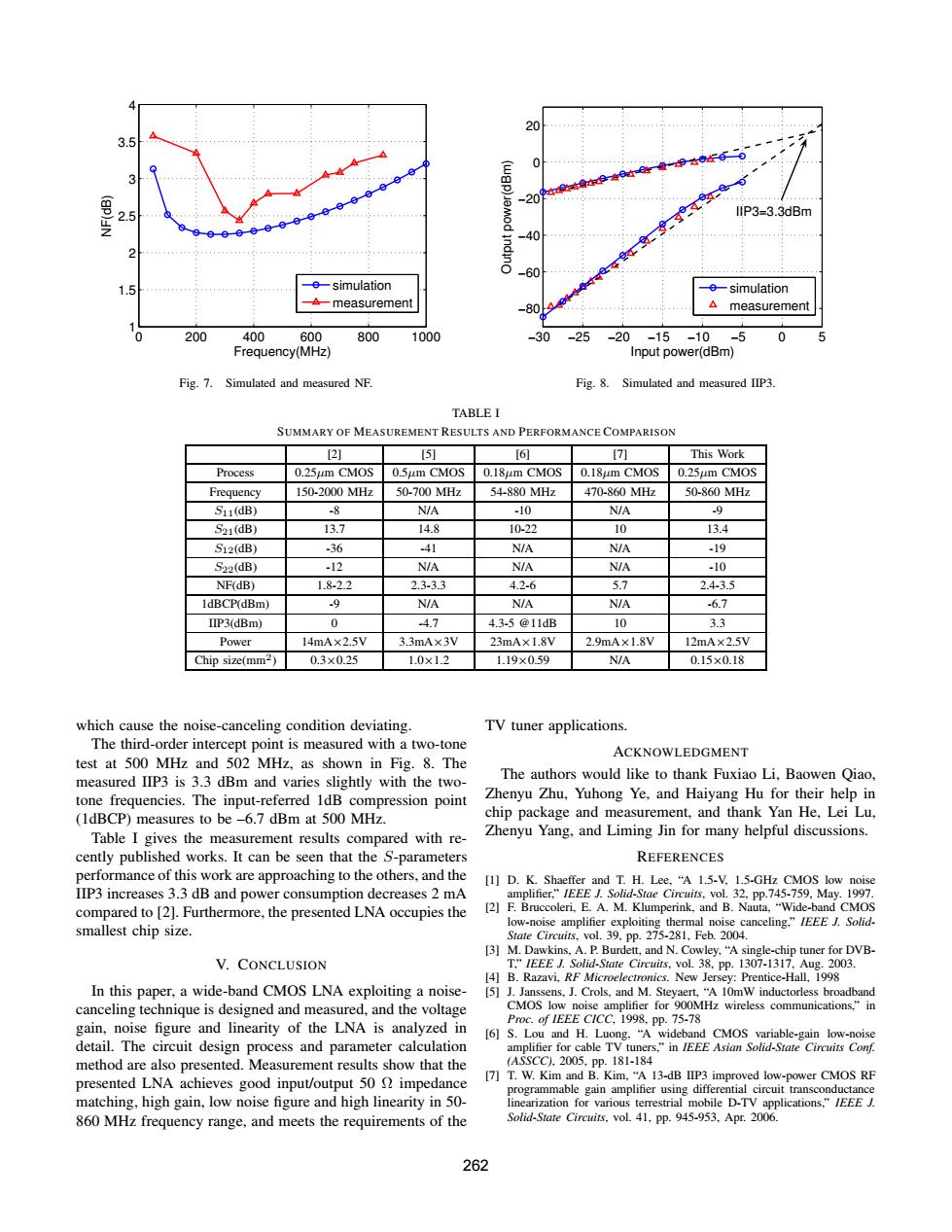
20 (wgp) IIP3-3.3dBm -simulation -e-simulation measurement measurement 200 400 600 800 1000 25 20 -15 -10 -5 0 5 Frequency(MHz) Input power(dBm) Fig.7. Simulated and measured NF. Fig.8. Simulated and measured IIP3 TABLE I SUMMARY OF MEASUREMENT RESULTS AND PERFORMANCE COMPARISON 2] [5 [6 刀 This Work Process 0.25um CMOS 0.5um CMOS 0.18um CMOS 0.18um CMOS 0.25um CMOS Frequency 150-2000MHz 50-700MHz 54-880MHz 470-860MHz 50-860MHz S11(dB) -8 N/A -10 N/A 9 S21(dB) 13.7 14.8 10-22 10 13.4 S12(dB) .36 -41 NIA NIA -19 S22(dB) -12 N/A N/A N/A -10 NF(dB) 1.8-2.2 2.3-3.3 4.2-6 5.7 2.43.5 IdBCP(dBm) 9 N/A N/A N/A -6.7 IIP3(dBm) 0 -4.7 4.3-5@11dB 10 3.3 Power 14mA×2.5V 3.3mA×3V 23mA×1.8V 2.9mA×1.8V 12mA×2.5V Chip size(mm2) 0.3×0.25 1.0×1.2 1.19×0.59 N/A 0.15×0.18 which cause the noise-canceling condition deviating. TV tuner applications The third-order intercept point is measured with a two-tone ACKNOWLEDGMENT test at 500 MHz and 502 MHz,as shown in Fig.8.The measured IIP3 is 3.3 dBm and varies slightly with the two- The authors would like to thank Fuxiao Li,Baowen Qiao, tone frequencies.The input-referred 1dB compression point Zhenyu Zhu,Yuhong Ye,and Haiyang Hu for their help in (1dBCP)measures to be-6.7 dBm at 500 MHz. chip package and measurement,and thank Yan He,Lei Lu, Table I gives the measurement results compared with re- Zhenyu Yang,and Liming Jin for many helpful discussions. cently published works.It can be seen that the S-parameters REFERENCES performance of this work are approaching to the others.and the [1]D.K.Shaeffer and T.H.Lee,"A 1.5-V.1.5-GHz CMOS low noise IIP3 increases 3.3 dB and power consumption decreases 2 mA amplifier,"IEEE J.Solid-Stae Circuits,vol.32,pp.745-759,May.1997 compared to [2].Furthermore,the presented LNA occupies the [2]F.Bruccoleri,E.A.M.Klumperink,and B.Nauta,"Wide-band CMOS low-noise amplifier exploiting thermal noise canceling,"IEEE /Solid. smallest chip size. State Circuits,vol.39,pp.275-281,Feb.2004. [3]M.Dawkins,A.P.Burdett,and N.Cowley,"A single-chip tuner for DVB- V.CONCLUSION T:"IEEE J.Solid-State Circuits.vol38.pp.1307-1317.Aug.2003. [4]B.Razavi.RF Microelectronics.New Jersey:Prentice-Hall.1998 In this paper,a wide-band CMOS LNA exploiting a noise- [5]J.Janssens.J.Crols,and M.Steyaert,"A 10mW inductorless broadband canceling technique is designed and measured,and the voltage CMOS low noise amplifier for 900MHz wireless communications,"in gain,noise figure and linearity of the LNA is analyzed in Proc.of IEEE CICC,1998.pp.75-78 [6]S.Lou and H.Luong."A wideband CMOS variable-gain low-noise detail.The circuit design process and parameter calculation amplifier for cable TV tuners,"in IEEE Asian Solid-State Circuits Conf. method are also presented.Measurement results show that the (ASSCC,2005,Pp.181-184 presented LNA achieves good input/output 50 impedance [7]T.W.Kim and B.Kim,"A 13-dB IIP3 improved low-power CMOS RF programmable gain amplifier using differential circuit transconductance matching,high gain,low noise figure and high linearity in 50- linearization for various terrestrial mobile D-TV applications,"IEEE. 860 MHz frequency range,and meets the requirements of the Solid-State Circuits.vol.41.pp.945-953.Apr.2006. 2620 200 400 600 800 1000 1 1.5 2 2.5 3 3.5 4 Frequency(MHz) NF(dB) simulation measurement Fig. 7. Simulated and measured NF. −30 −25 −20 −15 −10 −5 0 5 −80 −60 −40 −20 0 20 Input power(dBm) Output power(dBm) IIP3=3.3dBm simulation measurement Fig. 8. Simulated and measured IIP3. TABLE I SUMMARY OF MEASUREMENT RESULTS AND PERFORMANCE COMPARISON [2] [5] [6] [7] This Work Process 0.25µm CMOS 0.5µm CMOS 0.18µm CMOS 0.18µm CMOS 0.25µm CMOS Frequency 150-2000 MHz 50-700 MHz 54-880 MHz 470-860 MHz 50-860 MHz S11(dB) -8 N/A -10 N/A -9 S21(dB) 13.7 14.8 10-22 10 13.4 S12(dB) -36 -41 N/A N/A -19 S22(dB) -12 N/A N/A N/A -10 NF(dB) 1.8-2.2 2.3-3.3 4.2-6 5.7 2.4-3.5 1dBCP(dBm) -9 N/A N/A N/A -6.7 IIP3(dBm) 0 -4.7 4.3-5 @11dB 10 3.3 Power 14mA×2.5V 3.3mA×3V 23mA×1.8V 2.9mA×1.8V 12mA×2.5V Chip size(mm2 ) 0.3×0.25 1.0×1.2 1.19×0.59 N/A 0.15×0.18 which cause the noise-canceling condition deviating. The third-order intercept point is measured with a two-tone test at 500 MHz and 502 MHz, as shown in Fig. 8. The measured IIP3 is 3.3 dBm and varies slightly with the twotone frequencies. The input-referred 1dB compression point (1dBCP) measures to be –6.7 dBm at 500 MHz. Table I gives the measurement results compared with recently published works. It can be seen that the S-parameters performance of this work are approaching to the others, and the IIP3 increases 3.3 dB and power consumption decreases 2 mA compared to [2]. Furthermore, the presented LNA occupies the smallest chip size. V. CONCLUSION In this paper, a wide-band CMOS LNA exploiting a noisecanceling technique is designed and measured, and the voltage gain, noise figure and linearity of the LNA is analyzed in detail. The circuit design process and parameter calculation method are also presented. Measurement results show that the presented LNA achieves good input/output 50 Ω impedance matching, high gain, low noise figure and high linearity in 50- 860 MHz frequency range, and meets the requirements of the TV tuner applications. ACKNOWLEDGMENT The authors would like to thank Fuxiao Li, Baowen Qiao, Zhenyu Zhu, Yuhong Ye, and Haiyang Hu for their help in chip package and measurement, and thank Yan He, Lei Lu, Zhenyu Yang, and Liming Jin for many helpful discussions. REFERENCES [1] D. K. Shaeffer and T. H. Lee, “A 1.5-V, 1.5-GHz CMOS low noise amplifier,” IEEE J. Solid-Stae Circuits, vol. 32, pp.745-759, May. 1997. [2] F. Bruccoleri, E. A. M. Klumperink, and B. Nauta, “Wide-band CMOS low-noise amplifier exploiting thermal noise canceling,” IEEE J. SolidState Circuits, vol. 39, pp. 275-281, Feb. 2004. [3] M. Dawkins, A. P. Burdett, and N. Cowley, “A single-chip tuner for DVBT,” IEEE J. Solid-State Circuits, vol. 38, pp. 1307-1317, Aug. 2003. [4] B. Razavi, RF Microelectronics. New Jersey: Prentice-Hall, 1998 [5] J. Janssens, J. Crols, and M. Steyaert, “A 10mW inductorless broadband CMOS low noise amplifier for 900MHz wireless communications,” in Proc. of IEEE CICC, 1998, pp. 75-78 [6] S. Lou and H. Luong, “A wideband CMOS variable-gain low-noise amplifier for cable TV tuners,” in IEEE Asian Solid-State Circuits Conf. (ASSCC), 2005, pp. 181-184 [7] T. W. Kim and B. Kim, “A 13-dB IIP3 improved low-power CMOS RF programmable gain amplifier using differential circuit transconductance linearization for various terrestrial mobile D-TV applications,” IEEE J. Solid-State Circuits, vol. 41, pp. 945-953, Apr. 2006. 262