正在加载图片...
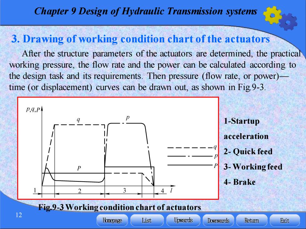
Chapter 9 Design of Hydraulic Transmission systems 3.Drawing of working condition chart of the actuators After the structure parameters of the actuators are determined,the practical working pressure,the flow rate and the power can be calculated according to the design task and its requirements.Then pressure(flow rate,or power)- time(or displacement)curves can be drawn out,as shown in Fig9-3. P.q,Pk 1-Startup acceleration 2-Quick feed 3-Working feed 4-Brake 47 Fig.9-3 Working condition chart of actuators 12 Homepage List Upwards Dowrwards Retumn Exit Chapter 9 Design of Hydraulic Transmission systems 12 3. Drawing of working condition chart of the actuators After the structure parameters of the actuators are determined, the practical working pressure, the flow rate and the power can be calculated according to the design task and its requirements. Then pressure (flow rate, or power)— time (or displacement) curves can be drawn out, as shown in Fig.9-3. Fig.9-3 Working condition chart of actuators 1-Startup acceleration 2- Quick feed 3- Working feed 4- Brake