Chapter 9 Design of Hydraulic Transmission systems Chapter list 9.1 The Approach for Design of Hydrostatic Circuits 9.2 A Design Example of Hydraulic Systems Homepage List Upwards Downwards Retmn Exit
Chapter 9 Design of Hydraulic Transmission systems 1 9.1 The Approach for Design of Hydrostatic Circuits 9.2 A Design Example of Hydraulic Systems Chapter list
Chapter 9 Design of Hydraulic Transmission systems Introduction The design of hydrostatic transmission systems is an important part of the whole mechanical design and also a summarizing and comprehensive application of knowledge in previous chapters. The aim of this chapter is to show through an example how hydrostatic transmission circuits can be designed to satisfy a given set of requirements. ) Homepage List Upwards Dowrwards Retumn Exit
Chapter 9 Design of Hydraulic Transmission systems 2 Introduction The design of hydrostatic transmission systems is an important part of the whole mechanical design and also a summarizing and comprehensive application of knowledge in previous chapters. The aim of this chapter is to show through an example how hydrostatic transmission circuits can be designed to satisfy a given set of requirements
Chapter 9 Design of Hydraulic Transmission systems 9.1 The Approach for Design of Hydrostatic systems 9.1.1 Determination of design requirements 9.1.2 Analysis for working conditions and determination of main parameters 9.1.3 Determination of hydraulic system diagram 9.1.4 Calculation and selection of hydraulic components 9.1.5 Performance check for a hydraulic system designed 9.1.6 Drawing of working diagrams and technical documents 3 Homepage List Upwards Downwards Retumn Exit
Chapter 9 Design of Hydraulic Transmission systems 3 9.1 The Approach for Design of Hydrostatic systems 9.1.1 Determination of design requirements 9.1.2 Analysis for working conditions and determination of main parameters 9.1.3 Determination of hydraulic system diagram 9.1.4 Calculation and selection of hydraulic components 9.1.5 Performance check for a hydraulic system designed 9.1.6 Drawing of working diagrams and technical documents
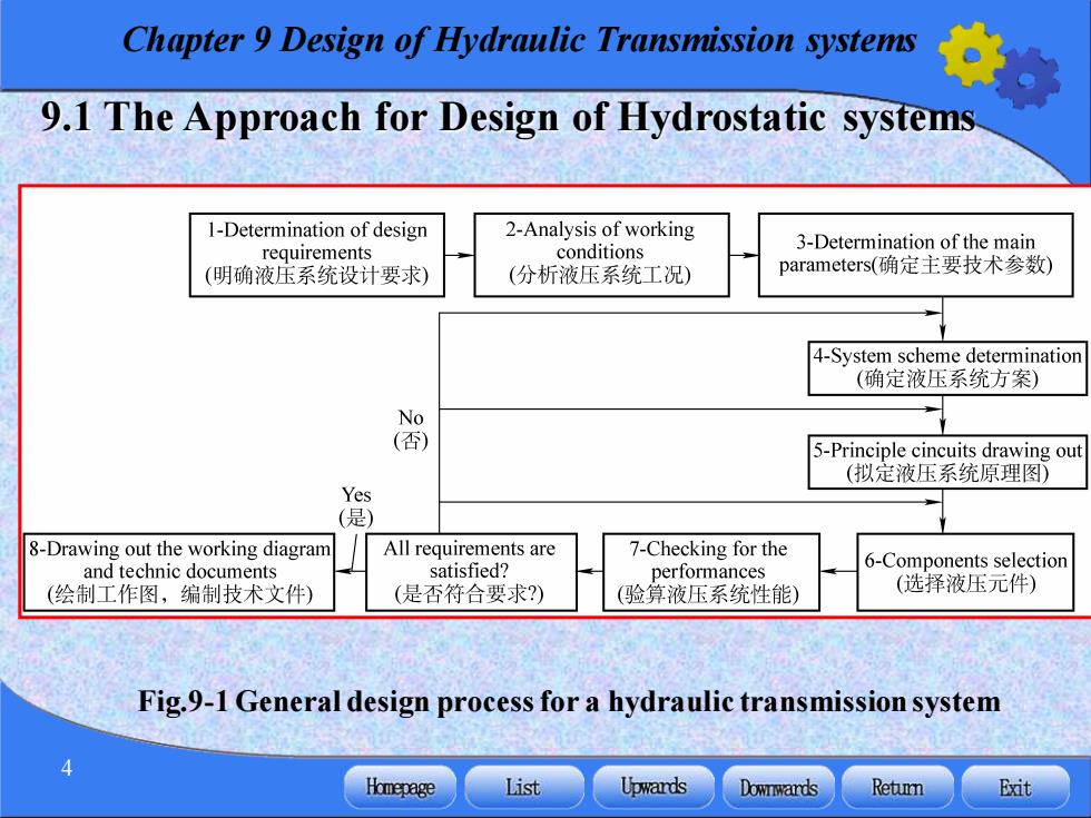
Chapter 9 Design of Hydraulic Transmission systems 9.1 The Approach for Design of Hydrostatic systems 1-Determination of design 2-Analysis of working conditions 3-Determination of the main requirements (明确液压系统设计要求) (分析液压系统工况) parameters(确定主要技术参数) 4-System scheme determination (确定液压系统方案) No (否) 5-Principle cincuits drawing out (拟定液压系统原理图) Yes (是) 8-Drawing out the working diagram All requirements are 7-Checking for the and technic documents satisfied? performances 6-Components selection (绘制工作图,编制技术文件) (是否符合要求?) (验算液压系统性能) (选择液压元件) Fig.9-1 General design process for a hydraulic transmission system Homepage List Upwards Downwards Retu Exit
Chapter 9 Design of Hydraulic Transmission systems 4 9.1 The Approach for Design of Hydrostatic systems Fig.9-1 General design process for a hydraulic transmission system
Chapter 9 Design of Hydraulic Transmission systems 9.1.1 Determination of design requirements Before a hydraulic system is designed,the working conditions of the mainframe in the mechanical equipment must be analyzed. 1.The purpose of the mainframe,the overall arrangement,the limitations to the position of the hydraulic devices and their sizes. 2.The mainframe work cycle,the system actions,their sequence, interlock function,automatization. 3.The load on actuators and the ranges of speed,motion stability position accuracy,conversion accuracy,etc. 4.Working environment and working conditions. 5.Working efficiency,safety,reliability,cost,etc Homepage List Upwards Downwards Retumn Exit
Chapter 9 Design of Hydraulic Transmission systems 5 9.1.1 Determination of design requirements Before a hydraulic system is designed, the working conditions of the mainframe in the mechanical equipment must be analyzed. 1. The purpose of the mainframe, the overall arrangement, the limitations to the position of the hydraulic devices and their sizes. 2. The mainframe work cycle, the system actions, their sequence, interlock function, automatization. 3. The load on actuators and the ranges of speed, motion stability, position accuracy, conversion accuracy, etc. 4. Working environment and working conditions. 5. Working efficiency, safety, reliability, cost, etc
Chapter 9 Design of Hydraulic Transmission systems 9.1.2 Analysis for working conditions and determination of main parameters Analysis of working conditions dynamic parameters(Fig.9-2a) Includes two parts of movement parameters(Fig.9-2b) 1)Dynamic parameters analysis A load diagram can be drawn out based on the determined extrinsic loads,see Fig.9-2a,which is load chart.The load chart is actually a load-displacement (F-1)curve Homepage List Upwards Downwards Retumn Exit
Chapter 9 Design of Hydraulic Transmission systems 6 1. Analysis of working conditions 1)Dynamic parameters analysis A load diagram can be drawn out based on the determined extrinsic loads, see Fig.9-2a, which is load chart. The load chart is actually a load-displacement (F-l)curve . dynamic parameters (Fig.9-2a) Includes two parts of movement parameters (Fig.9-2b) 9.1.2 Analysis for working conditions and determination of main parameters
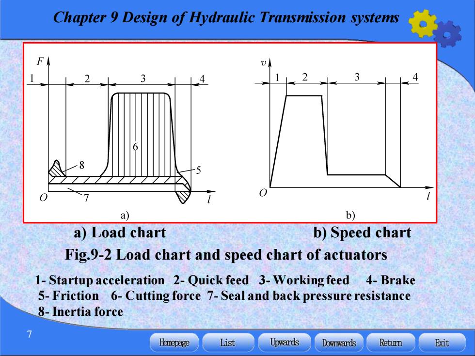
Chapter 9 Design of Hydraulic Transmission systems F a) b) a)Load chart b)Speed chart Fig.9-2 Load chart and speed chart of actuators 1-Startup acceleration 2-Quick feed 3-Working feed 4-Brake 5-Friction 6-Cutting force 7-Seal and back pressure resistance 8-Inertia force Homepage List Upwards Downwards Retumn Exit
Chapter 9 Design of Hydraulic Transmission systems 7 a) Load chart b) Speed chart Fig.9-2 Load chart and speed chart of actuators 1- Startup acceleration 2- Quick feed 3- Working feed 4- Brake 5- Friction 6- Cutting force 7- Seal and back pressure resistance 8-Inertia force

Chapter 9 Design of Hydraulic Transmission systems 2)Movement parameters analysis Fig.9-2b is a speed-displacement (v-1)curve drawn to express the speed of each actuator in different phases,it is called speed chart. When the actuator works in line reciprocating,the extrinsic load will be F=F+F+F (9-1) (1)The working load F Homepage List Upwards Downwards Retumn Exit
Chapter 9 Design of Hydraulic Transmission systems 8 2)Movement parameters analysis Fig.9-2b is a speed-displacement (v-l)curve drawn to express the speed of each actuator in different phases, it is called speed chart. When the actuator works in line reciprocating, the extrinsic load will be F F F F = + + L f a (9-1) (1) The working load FL
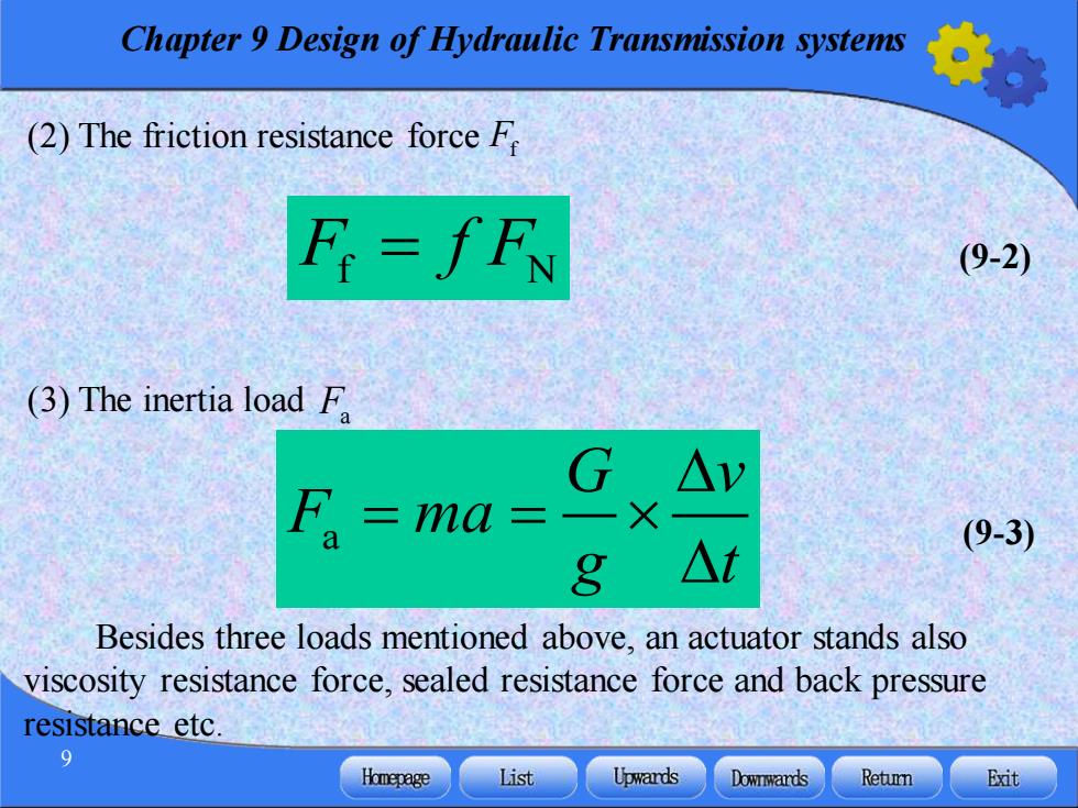
Chapter 9 Design of Hydraulic Transmission systems (2)The friction resistance force F F=fFN (9-2) (3)The inertia load F G△v F =ma= 一X (9-3) 8 △t Besides three loads mentioned above,an actuator stands also viscosity resistance force,sealed resistance force and back pressure resistance etc. Homepage List Upwards Downwards Retumn Exit
Chapter 9 Design of Hydraulic Transmission systems 9 (2) The friction resistance force Ff F f F f N = (9-2) (3) The inertia load Fa Besides three loads mentioned above, an actuator stands also viscosity resistance force, sealed resistance force and back pressure resistance etc. a (9-3) G v F ma g t = =
Chapter 9 Design of Hydraulic Transmission systems 2.Determination of main parameters The working pressure for actuators can be selected according to the largest load in the load chart(see Tab.9-1)or the mainframe type(see Tab.9-2).However the largest flow rate must be calculated by the highest speed shown in the speed chart. The lowest working speed vinor i(n=2min/60) must satisfy the following requirements: For cylinders ∠Vmin For motors qmin≤0min M 10 Homepage List Upwards Downwards Retumn Exit
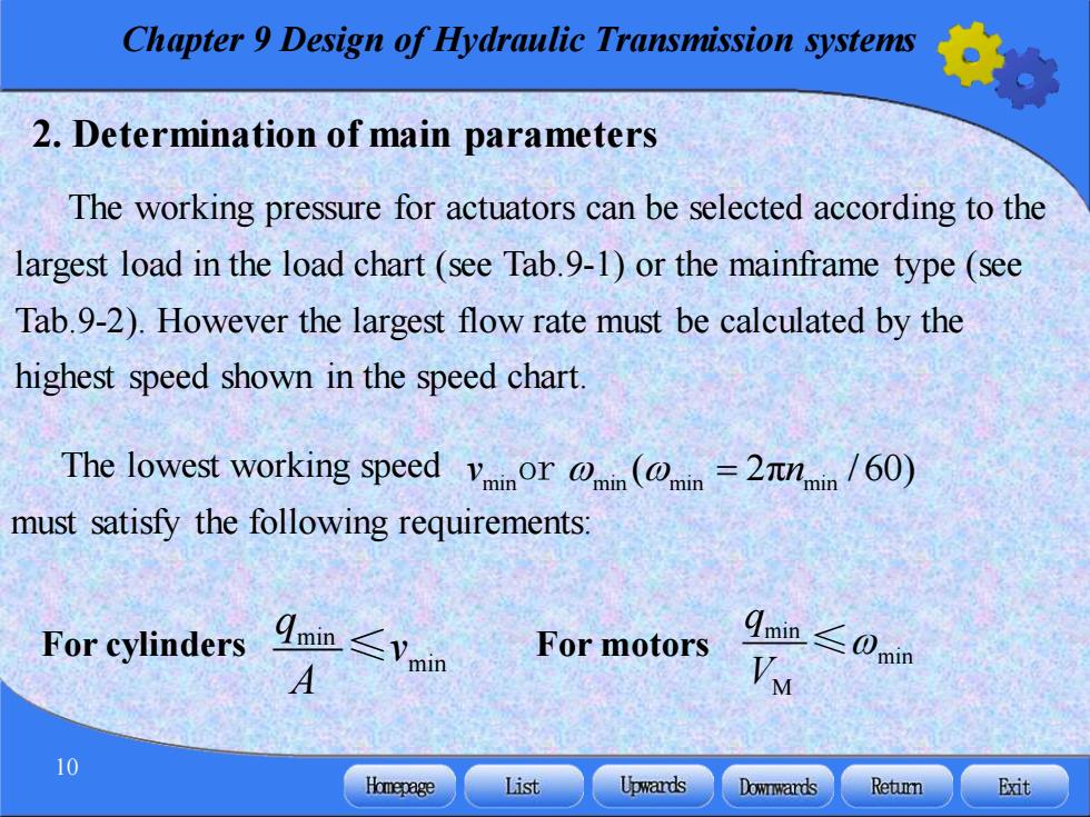
Chapter 9 Design of Hydraulic Transmission systems 10 2. Determination of main parameters The working pressure for actuators can be selected according to the largest load in the load chart (see Tab.9-1) or the mainframe type (see Tab.9-2). However the largest flow rate must be calculated by the highest speed shown in the speed chart. The lowest working speed must satisfy the following requirements: min min q v A ≤ min min M q V For cylinders For motors ≤ min min min min v n or ( 2 = π / 60)