Chapter I Introduction to Hydraulic and Pneumatic Transmission Chapter list 1.1 Study on Hydraulic and Pneumatic Transmission 1.2 Operating Principles of Hydraulic Transmission 1.3 Composing of Hydraulic Transmission System 1.4 Features of Hydraulic and Pneumatic Transmission 1.5 The Development History and Applications of Hydraulic and Pneumatic Technology Homepage List Upwards Downwards Retumn Exit
Chapter 1 Introduction to Hydraulic and Pneumatic Transmission 1 1.1 Study on Hydraulic and Pneumatic Transmission 1.2 Operating Principles of Hydraulic Transmission 1.3 Composing of Hydraulic Transmission System 1.4 Features of Hydraulic and Pneumatic Transmission 1.5 The Development History and Applications of Hydraulic and Pneumatic Technology Chapter list
Chapter I Introduction to Hydraulic and Pneumatic Transmission 1.1 Study on Hydraulic and Pneumatic Transmission Hydraulic and pneumatic transmission is a part of fluid power transmission,which is a discipline based on the medium energy of compressive fluid(i.e.,pressure oil or compressive air),to accomplish mechanical transmission. The main study of this course: (1)Operating principle,sub-circuit and the hydraulic system. p (2)Physical performances and static/dynamic characters of fluid. (3)Designs of the Hydraulic and pneumatic system. Homepage List Upwards Downwards Retun Exit
Chapter 1 Introduction to Hydraulic and Pneumatic Transmission 2 1.1 Study on Hydraulic and Pneumatic Transmission Hydraulic and pneumatic transmission is a part of fluid power transmission, which is a discipline based on the medium energy of compressive fluid (i.e., pressure oil or compressive air) , to accomplish mechanical transmission. The knowledge points of this chapter: The basic operating principle, buildup of the system, the characters and application of hydraulic and pneumatic transmission, and the trend of its development. The difficulty of this chapter: Grasp of the two important characters which obtain fluid power transmission. The main study of this course: (1) Operating principle, sub-circuit and the hydraulic system. (2) Physical performances and static/dynamic characters of fluid. (3) Designs of the Hydraulic and pneumatic system
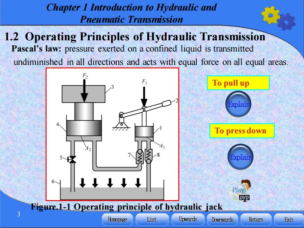
Chapter I Introduction to Hydraulic and Pneumatic Transmission 1.2 Operating Principles of Hydraulic Transmission Pascal's law:pressure exerted on a confined liquid is transmitted undiminished in all directions and acts with equal force on all equal areas. To pull up To press down Explain DVD Figure.1-1 Operating principle of hydraulic jack Homepage List Upwards Downwards Retun Exit
Chapter 1 Introduction to Hydraulic and Pneumatic Transmission 3 1.2 Operating Principles of Hydraulic Transmission Pascal’s law: pressure exerted on a confined liquid is transmitted undiminished in all directions and acts with equal force on all equal areas. Figure.1-1 Operating principle of hydraulic jack To pull up To press down
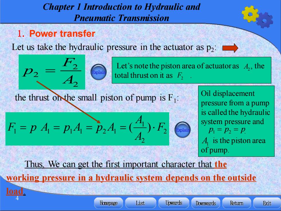
Chapter I Introduction to Hydraulic and Pneumatic Transmission 1.Power transfer Let us take the hydraulic pressure in the actuator as p2: F2 Let's note the piston area of actuatoras 4,the plai total thrust on it as F, the thrust on the small piston of pump is F: Oil displacement pressure from a pump is called the hydraulic F=pA=B4=4=(4)E system pressure and P=P2=P A is the piston area of pump Thus,We can get the first important character that the working pressure in a hydraulic system depends on the outside Homepage List Upwards Downwards Retun Exit
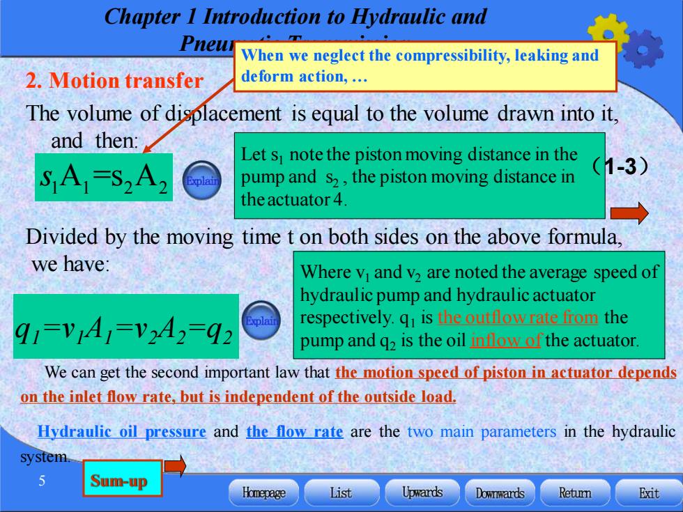
Chapter 1 Introduction to Hydraulic and Pneumatic Transmission 4 (1-1) (1-2) 1. Power transfer Thus, We can get the first important character that the working pressure in a hydraulic system depends on the outside load. 2 2 2 F p A = 2 2 1 1 1 1 1 2 1 ( ) F A A F = p A = p A = p A = Oil displacement pressure from a pump is called the hydraulic system pressure and . is the piston area of pump. Let us take the hydraulic pressure in the actuator as p2 : the thrust on the small piston of pump is F1 : Let’s note the piston area of actuator as , the total thrust on it as . F2 A2 1 2 p p p = = A1
Chapter I Introduction to Hydraulic and Pneur When we neglect the compressibility,leaking and 2.Motion transfer deform action,. The volume of displacement is equal to the volume drawn into it, and then: Let s note the piston moving distance in the SA=S2A2 pump and s2,the piston moving distance in (1-3) the actuator 4 Divided by the moving time t on both sides on the above formula. we have: Where v and v2 are noted the average speed of hydraulic pump and hydraulic actuator 91=V1A1=V2A2=92 respectively.q is the outflow rate from the pump and q2 is the oil inflow of the actuator We can get the second important law that the motion speed of piston in actuator depends on the inlet flow rate,but is independent of the outside load Hydraulic oil pressure and the flow rate are the two main parameters in the hydraulic system. 5 Sum-up Homepage List Upwards Downwards Retumn Exit
Chapter 1 Introduction to Hydraulic and Pneumatic Transmission 5 (1-4) We can get the second important law that the motion speed of piston in actuator depends on the inlet flow rate, but is independent of the outside load. Hydraulic oil pressure and the flow rate are the two main parameters in the hydraulic system. s1 1 2 2 A =s A 2. Motion transfer The volume of displacement is equal to the volume drawn into it, and then: Let s1 note the piston moving distance in the pump and s2 , the piston moving distance in theactuator 4. (1-3) Divided by the moving time t on both sides on the above formula, we have: Where v1 and v2 are noted the average speed of hydraulic pump and hydraulic actuator respectively. q1 is the outflow rate from the pump and q2 is the oil inflow of the actuator. q1=v1A1=v2A2=q2 When we neglect the compressibility, leaking and deform action, . Sum-up
Chapter I Introduction to Hydraulic and Pneumatic Transmission 1.3 Composing of Hydraulic Transmission System 1-Hydraulic pump 2-Adjustable throttle valve 3-Closed center directional valve 4-Hydraulic actuator 5-Working load 6-Relief valve 7-Filter 8-Reservoir (tank)-A container for storage Semi-structure sketch(visual) Symbol sketch (abstract) of liquid in a fluid power system. Figure.1-2 Principle of a typical hydraulic system Homepage List Upward达s Downwards Retumn Exit
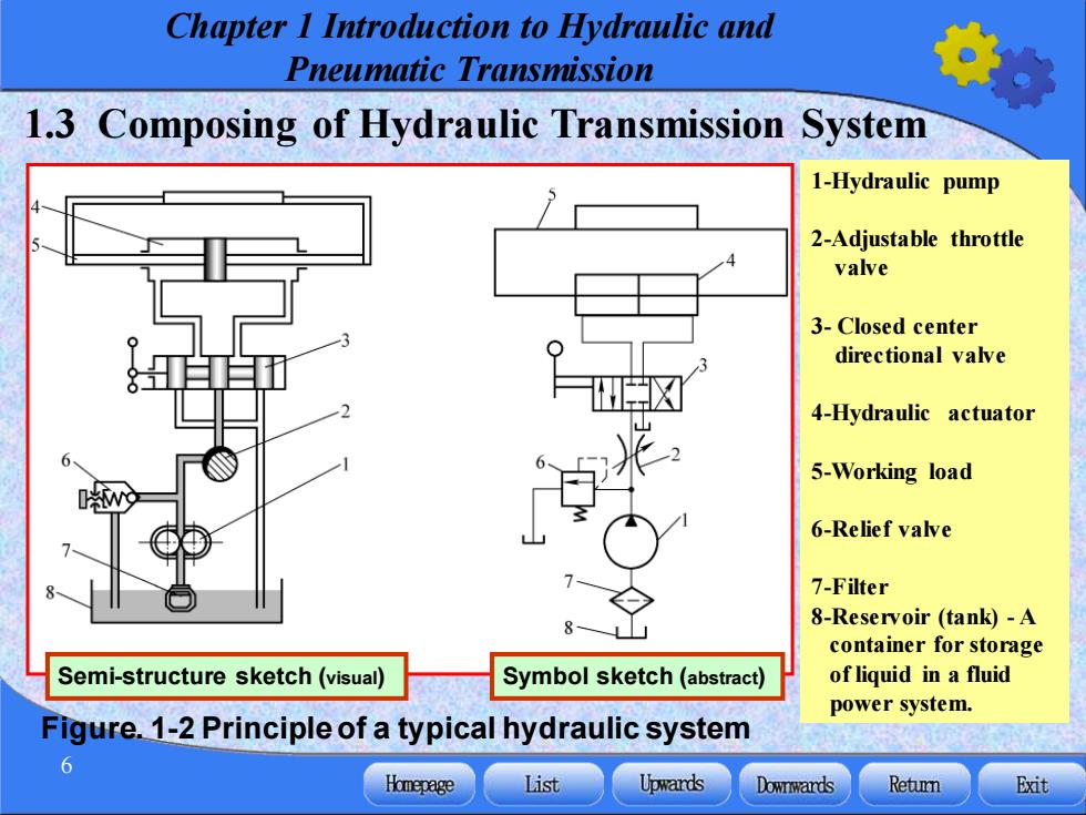
Chapter 1 Introduction to Hydraulic and Pneumatic Transmission 6 1.3 Composing of Hydraulic Transmission System Figure. 1-2 Principle of a typical hydraulic system 1-Hydraulic pump 2-Adjustable throttle valve 3- Closed center directional valve 4-Hydraulic actuator 5-Working load 6-Relief valve 7-Filter 8-Reservoir (tank) - A container for storage of liquid in a fluid power system. Semi-structure sketch (visual) Symbol sketch (abstract)

Chapter I Introduction to Hydraulic and Pneumatic Transmission When pump 1 driven by a motor is operating,the hydraulic oil flows from To shift left reservoir 8 pass filter 7, through inlet and outlet of pump,via adjustable throttle valve 2 and stops at the "mid position"of the valve 3. Or to shift right Mid position Valve 3 is a shift valve Valve 2 is used to regulate the speed of an actuator Valve 6 is used to set the DVD pressure of the system. Homepage List Upwards Downwards Retun Exit
Chapter 1 Introduction to Hydraulic and Pneumatic Transmission 7 When pump 1 driven by a motor is operating, the hydraulic oil flows from reservoir 8 pass filter 7, through inlet and outlet of pump, via adjustable throttle valve 2 and stops at the “mid position” of the valve 3. To shift left Or to shift right Mid position Valve 3 is a shift valve Valve 2 is used to regulate the speed of an actuator Valve 6 is used to set the pressure of the system

Chapter I Introduction to Hydraulic and Pneumatic Transmission From the mentioned above,we can see that a hydraulic system can be divided into five logical segments: (1)Power input segment (energy )to transfer the mechanical energy to hydraulic power.It usually consists of one or several pumps.(as such No.1.pump on the Fig.1-2) (2)Power output segment (actuator):to transfer the hydraulic power to the mechanical energy.(such as actuator 4 on the Fig.1-2) (3)Control components:it can be used in a hydraulic system to restrict the pressure,regulate the speed of actuator or the motion direction; (such as No.6,No2.,and No.3.on the Fig.1-2) (4)Assistant components it can be used to keep system working. (such as No.7,and No.8.on the Fig.1-2) (g5) Homepage List Upwards Downwards Retun Exit
Chapter 1 Introduction to Hydraulic and Pneumatic Transmission 8 From the mentioned above, we can see that a hydraulic system can be divided into five logical segments: (1)Power input segment (energy ): to transfer the mechanical energy to hydraulic power. It usually consists of one or several pumps. (as such No.1.pump on the Fig.1-2) (2)Power output segment (actuator): to transfer the hydraulic power to the mechanical energy. (such as actuator 4 on the Fig.1-2) (3) Control components: it can be used in a hydraulic system to restrict the pressure, regulate the speed of actuator or the motion direction; (such as No.6, No2., and No.3. on the Fig.1-2) (4) Assistant components : it can be used to keep system working. (such as No.7, and No.8. on the Fig.1-2) (5)Working oil: hydraulic oil (medium)
Chapter I Introduction to Hydraulic and Pneumatic Transmission 1.4 Features of Hydraulic and Pneumatic Transmission 1.The advantages a Advantages: Advant 1)The air can be obtained from and expelled to the 1)The atmosphere. power co 2)It is of low viscosity and lower pressure loss in 2)It ha pipes 3)It ha 3)It is of low working pressure. 4)The 4)The pneumatic transmission needs easy servicing 5)It ca 5)Safety 6)The on. 2.The advan 7)The Disad小vantages: motion. 1)The working stabilities are poorer than those of Disadva hydraulic transmission system. 1)Ine 2)The push force of pneumatic transmission is not 2)Hig strong enough The details can be found in your textbook. c69
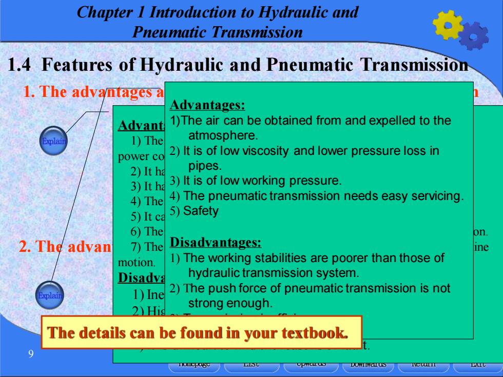
Chapter 1 Introduction to Hydraulic and Pneumatic Transmission 9 2. The advantages and disadvantages of pneumatic transmission 1. The advantages and disadvantages of hydraulic transmission 1.4 Features of Hydraulic and Pneumatic Transmission Advantages: 1) The hydraulic equipment system has smaller volume, light, high power consistency and compact configuration at a given power. 2) It has good working stability. 3) It has a wide range of speed regulation. 4) The hydraulic transmission can be easily realized automation. 5) It can prevent from over-load. 6) The hydraulic system is easier in design, fabrication and application. 7) The hydraulic system is easier than machine equipment in doing line motion. Disadvantages: 1) Inevitable Oil leaks; 2) High working temperature; 3) High cost; 4) It is difficult to find the reasons of fault. Advantages: 1)The air can be obtained from and expelled to the atmosphere. 2) It is of low viscosity and lower pressure loss in pipes. 3) It is of low working pressure. 4) The pneumatic transmission needs easy servicing. 5) Safety Disadvantages: 1) The working stabilities are poorer than those of hydraulic transmission system. 2) The push force of pneumatic transmission is not strong enough. 3) Transmission inefficiency. The details can be found in your textbook

Chapter I Introduction to Hydraulic and Pneumatic Transmission 1.5 The Development History and Applications of Hydraulic and Pneumatic Transmission Hydraulic transmission has been experiencing the process as follows.(3 stages) The 17th century and the early 18th century-a productive period in the development of hydraulic theory The 18th century-This principle was first adopted.The first hydraulic pressure machine was manufactured in Britain late in the 18th century The 19th century until now-has a great application in Hydraulic and Pneumatic technology The details can be referred in your textbook. 10 Homepage List Upwards Downwards Retun Exit
Chapter 1 Introduction to Hydraulic and Pneumatic Transmission 10 Hydraulic transmission has been experiencing the process as follows. (3 stages) The 17th century and the early 18th century — a productive period in the development of hydraulic theory. The 18th century —This principle was first adopted. The first hydraulic pressure machine was manufactured in Britain late in the 18th century. The 19th century until now—has a great application in Hydraulic and Pneumatic technology. 1.5 The Development History and Applications of Hydraulic and Pneumatic Transmission The details can be referred in your textbook