附件24.5 Course Name Hvdraulic and Pneumatic Transmission Exam Date Name Student No Major Title No Signature Title Score ore Attentions::l、 Please check if the papers have five pages and whether it has missed page 2.Candidates for exam could not bring the paper,answer sheet and the draft paper out the examination hall after the examination. 1.Multiple Choice (1)Flow continuity equation is the expression-form of(C)in hydrodynamics and Bernoulli equation is the expression-form of(A)in hydrodynamics. A.Conservation law of energy B.Momentum theorem C.Law of conservation of mass D.Newton third law (2)Flow rate of liquid which moving through the orifice rise proportionately to the(A)of the area of orifice and(B)of pressure difference A.First power B.Square root C.Square D.Cube (3)(B)can withstand the negative load and (C)with the worst speed rigidity in the throttle speed-regulating circuit. A.Inlet throttle speed-regulating circuit B.Outlet throttle speed-regulating circuit C.Bypass throttle orifice speed-regulating circuit D.Volume speed-regulating circuit (4)The flow rate of the pump which bears zero load is often regarded as (B). A.practical flow-rate B.Theoretical flow-rate
附件 24.5 Course Name Hydraulic and Pneumatic Transmission Exam Date Name Student No Major Title No 1 2 3 4 5 6 7 8 Title Score Signature Score Attentions:1、 Please check if the papers have five pages and whether it has missed page 2、Candidates for exam could not bring the paper, answer sheet and the draft paper out the examination hall after the examination. 1. Multiple Choice (1) Flow continuity equation is the expression-form of ( C ) in hydrodynamics and Bernoulli equation is the expression-form of ( A ) in hydrodynamics. A. Conservation law of energy B. Momentum theorem C. Law of conservation of mass D. Newton third law (2) Flow rate of liquid which moving through the orifice rise proportionately to the ( A ) of the area of orifice and ( B ) of pressure difference. A. First power B. Square root C. Square D. Cube (3) ( B ) can withstand the negative load and ( C ) with the worst speed rigidity in the throttle speed-regulating circuit. A. Inlet throttle speed-regulating circuit B. Outlet throttle speed-regulating circuit C. Bypass throttle orifice speed-regulating circuit D. Volume speed-regulating circuit (4) The flow rate of the pump which bears zero load is often regarded as (B). A. practical flow-rate B. Theoretical flow-rate 1

附件24.5 C.Rated flow-rate D.Minimum flow-rate (5)We have known that single-rod piston cylinder have effective area A1=2A2, flow rate q.If the hydraulic cylinder achieve differential,then the flow rate of the large cavity is(D).If it is not the differential connections,then the flow rate of the small cavity is(A). A.0.5gB.1.5g C.1.75qD.2g (6)Horizontal Double-rod piston cylinder is connected to three position four way solenoid-operated directional conro valve in the hydraulic system.It is required that when the three position four way solenoid-operated directional control valve is on the condition of netral positionsthe pump is in a state of unloading and the cylinder is in a state of floating.The mid position function should be selected for (D).And then if the cylinder is in a state of motionless which should be selected for (B). A.O type B.M type C.Ytype D.Htype (7)In order to ensure the constant pressure difference of throttle when the load change. the speed-regulating valve always consists of throttle and (B)with series connection and then the bypass speed-regulating valve consists of throttle and(D)with parallel connection. A.Pressure redueing valve B.Fixed differential pressure-reducing valve C.Non-return valve D.Differential pressure reliefvalve (8)Rotating speed of the motor will (B),Output power of the pump will (C)when the torque driven by hydraulic motor is smaller in the volume speed-regulating circuit of fixed displacement pump-variable displacement motor. A.Enlarge B.Remain practically unchanged C.Decrease D.Zero 2.Fill in the blanks (1)Hydraulic transmission system consists of energ portionactuator portion control element、4 ssistant elemen坐、working oil. (2)The liquid have two flow state in the pipeline,viscous foree play a_leading role for aminar fow,inertial force play a leading role for turbulent.The liquid flow state can be judged by Revnolds number. (3)In order to eliminate the phenomenon of surrounded oil,most gear pumps are designed with relief grooves on the front and rear cover boards or floating sideboard.The chamber connects with the out-let port when the volume of the chamber changes from the maximum to zero,and with the inlet port when it changes back from zero to the
附件 24.5 C. Rated flow-rate D. Minimum flow-rate (5) We have known that single-rod piston cylinder have effective area A1 = 2A2, flow rate q. If the hydraulic cylinder achieve differential, then the flow rate of the large cavity is ( D ). If it is not the differential connections, then the flow rate of the small cavity is ( A ). A. 0.5q B. 1.5q C. 1.75q D. 2q (6) Horizontal Double-rod piston cylinder is connected to three position four way solenoid-operated directional control valve in the hydraulic system. It is required that when the three position four way solenoid-operated directional control valve is on the condition of neutral positions ,the pump is in a state of unloading and the cylinder is in a state of floating. The mid position function should be selected for ( D ). And then if the cylinder is in a state of motionless which should be selected for ( B ). A. O type B. M type C. Y type D. H type (7) In order to ensure the constant pressure difference of throttle when the load change, the speed-regulating valve always consists of throttle and ( B ) with series connection, and then the bypass speed-regulating valve consists of throttle and ( D ) with parallel connection. A. Pressure reducing valve B. Fixed differential pressure-reducing valve C. Non-return valve D. Differential pressure relief valve (8) Rotating speed of the motor will ( B ) , Output power of the pump will ( C )when the torque driven by hydraulic motor is smaller in the volume speed-regulating circuit of fixed displacement pump-variable displacement motor. A. Enlarge B. Remain practically unchanged C. Decrease D. Zero 2. Fill in the blanks (1) Hydraulic transmission system consists of energy portion 、actuator portion、 control elements 、assistant elements 、working oil . (2) The liquid have two flow state in the pipeline ,viscous force play a leading role for laminar flow,inertial force play a leading role for turbulent .The liquid flow state can be judged by Reynolds number. (3) In order to eliminate the phenomenon of surrounded oil ,most gear pumps are designed with relief grooves on the front and rear cover boards or floating sideboard. The chamber connects with the out-let port when the volume of the chamber changes from the maximum to zero, and with the inlet port when it changes back from zero to the 2

附件24.5 maximum. (4).In the speed-regulating circuit of variable displacement pump-variable displacement motor,for both situations of higher output torque at lower speed and higher output power at higher speed,first the displacement of motor is set to the maximum at low speeds and the speed is regulated by variable displacement pump;Secondly,at high speeds the displacement of pump is kept at maximal and the speed is regulated by variable displacement motor. (5)The pressure of hydraulic system depends on th 3.Answer the questions (1)Why speed-regulating valve can keep constant movement velocity of actuator stable? Referenced answers:Refer to the answers on the pages from 151 to 152 in your textbook (2)What are the characteristics of plunger cylinders? Referenced answers:Refer to the answers on the pages from 111 to 112 in your textbook. (3)Draw the flow-pressure characteristic curve of pressure-limiting variable vane pump and explain what occasion it is applicable to? Referenced answers:Refer to the answers on the pages from 82 to 84 in your textbook. (4)Draw the symbol of the O type three position four way solenoid-operated directional control valve,speed-regulating valve and pressure reducing valve. Referenced answers: 中
附件 24.5 maximum. (4). In the speed-regulating circuit of variable displacement pump-variable displacement motor , for both situations of higher output torque at lower speed and higher output power at higher speed , first the displacement of motor is set to the maximum at low speeds and the speed is regulated by variable displacement pump; Secondly, at high speeds the displacement of pump is kept at maximal and the speed is regulated by variable displacement motor . (5) The pressure of hydraulic system depends on the outside load. 3、Answer the questions (1) Why speed-regulating valve can keep constant movement velocity of actuator stable? Referenced answers: Refer to the answers on the pages from 151 to 152 in your textbook. (2) What are the characteristics of plunger cylinders? Referenced answers: Refer to the answers on the pages from 111 to 112 in your textbook. (3) Draw the flow- pressure characteristic curve of pressure-limiting variable vane pump and explain what occasion it is applicable to? Referenced answers: Refer to the answers on the pages from 82 to 84 in your textbook. (4) Draw the symbol of the O type three position four way solenoid-operated directional control valve, speed-regulating valve and pressure reducing valve. Referenced answers: 3

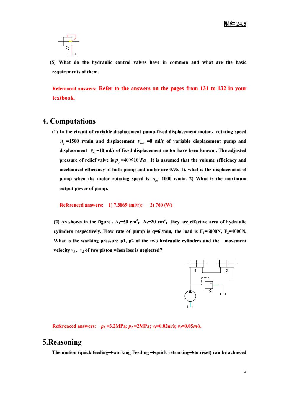
附件24.5 (5)What do the hydraulic control valves have in common and what are the basic requirements of them. Referenced answers:Refer to the answers on the pages from 131 to 132 in your textbook. 4.Computations (1)In the circuit of variable displacement pump-fixed displacement motor,rotating speed n=1500 r/min and displacement v mlr of variable displacement pump and displacement v10 mr of fixed displacement motor have been known.The adjusted pressure of relief valve.It is assumed that the volume efficieny and mechanical efficieney of both pump and motor are 95.1).what is the displacement of pump when the motor rotating speed is =1000 r/min.2)What is the maximum output power of pump. Referenced answers:1)7.3869(ml/r);2)760(W) (2)As shown in the figure,A=50 cm,A2=20 cm,they are effective area of hydrauli cylinders respectively.Flow rate of pump is q=6W/min,the load is F=6000N,F2=4000N. What is the working pressure pl,p2 of the two hydraulie cylinders and the movement velocityvv2 of two piston when loss is neglected? 2 Referenced answers:P:-3.2MPa;p:-2MPa;v.02m;v0.05m/ 5.Reasoning The motion(quick feeding->working Feeding-quick retracting-to reset)can be achieved
附件 24.5 (5) What do the hydraulic control valves have in common and what are the basic requirements of them. Referenced answers: Refer to the answers on the pages from 131 to 132 in your textbook. 4. Computations (1) In the circuit of variable displacement pump-fixed displacement motor,rotating speed =1500 r/min and displacement =8 ml/r of variable displacement pump and displacement =10 ml/r of fixed displacement motor have been known . The adjusted pressure of relief valve is p n max v mv y p =40×105 Pa . It is assumed that the volume efficiency and mechanical efficiency of both pump and motor are 0.95. 1). what is the displacement of pump when the motor rotating speed is =1000 r/min. 2) What is the maximum output power of pump. mn Referenced answers: 1) 7.3869 (ml/r); 2) 760 (W) (2) As shown in the figure , A1=50 cm2 ,A2=20 cm2 ,they are effective area of hydraulic cylinders respectively. Flow rate of pump is q=6l/min, the load is F1=6000N, F2=4000N. What is the working pressure p1, p2 of the two hydraulic cylinders and the movement velocity v1、v2 of two piston when loss is neglected? Referenced answers: p1 =3.2MPa; p2 =2MPa; v1=0.02m/s; v2=0.05m/s. 5.Reasoning The motion (quick feeding→working Feeding →quick retracting→to reset) can be achieved 4

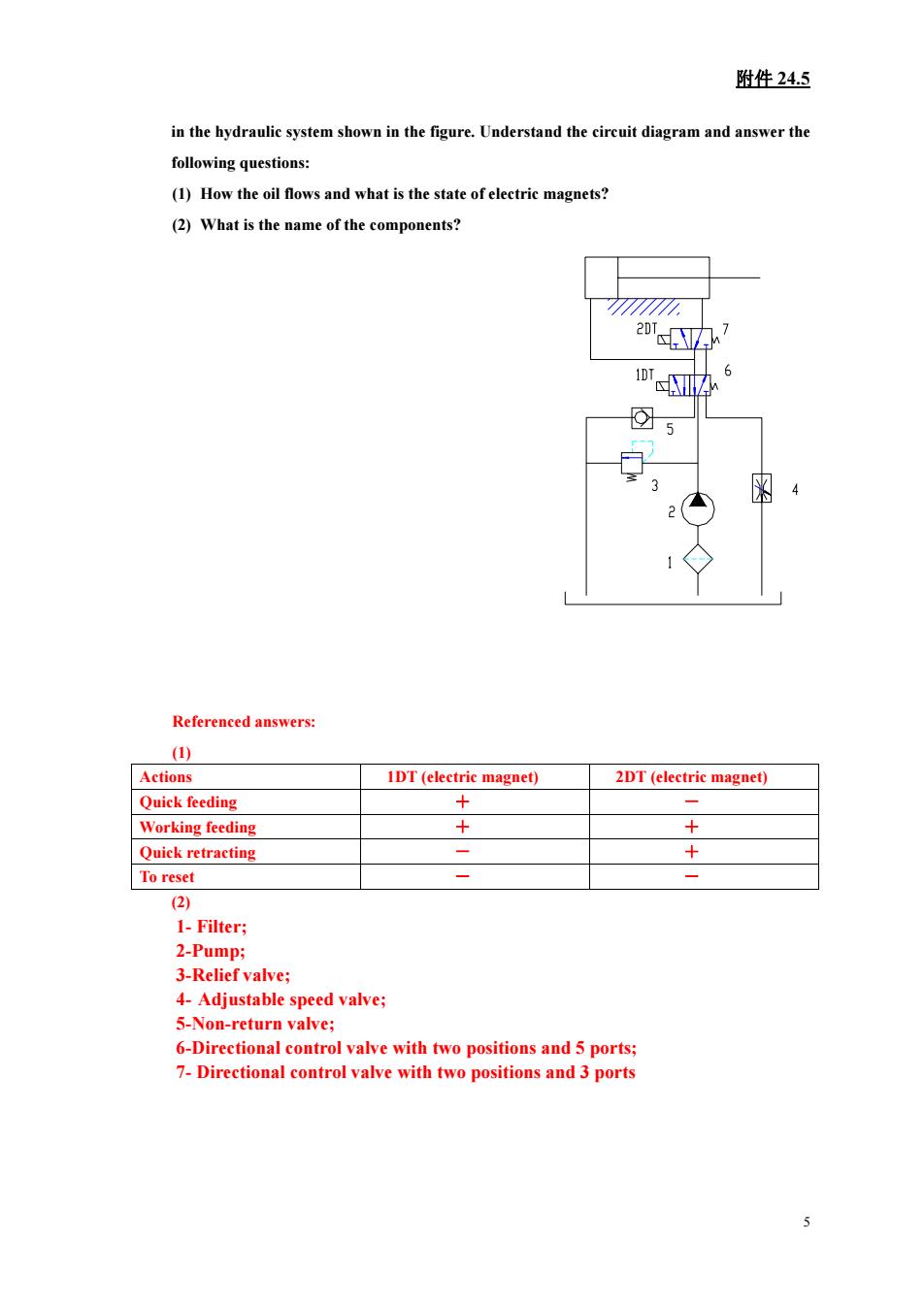
附件24.5 in the hydraulic system shown in the figure.Understand the circuit diagram and answer the following questions: (1)How the oil flows and what is the state of electric magnets? (2)What is the name of the components? Refereneed answers: () Actions IDT(electric magnet) 2DT (electric magnet) Quick feeding + Working feeding + Quick retracting +- To reset 1-Filter; 2-Pump: 3-Relief valve: 4-Adiustable speed valve: 5-Non-return valve; 6-Directional control valve with two positions and 5 ports: 7-Directional control valve with two positions and 3 ports
附件 24.5 in the hydraulic system shown in the figure. Understand the circuit diagram and answer the following questions: (1) How the oil flows and what is the state of electric magnets? (2) What is the name of the components? Referenced answers: (1) Actions 1DT (electric magnet) 2DT (electric magnet) Quick feeding + - Working feeding + + Quick retracting - + To reset - - (2) 1- Filter; 2-Pump; 3-Relief valve; 4- Adjustable speed valve; 5-Non-return valve; 6-Directional control valve with two positions and 5 ports; 7- Directional control valve with two positions and 3 ports 5