附件24.3 Problems from 《ydraulic and Pneumatic Transmission》 S M Chen,Fuzhou University,P.R.China Chapter 1 1-1 What are the differences and similarities among hydraulic pressure transmission,pneumatic pressure 1-2 How many parts does a hydraulic or pneumatic pressure transmission system consist of?What are they and what are their functions? 1-3 There are two significant features and two basic parameters in hydraulic or pneumatic pressure transmission eration.What are they? 1-4 How to build a circuit of hydraulic system? Chapter 2 2-1 A hydraulic cylinder has a volume of 50L at the atmospheric pressure,as the pressure increases the volume decreases to 9L what is the rising value of the pressure?The hydraulic ol bulk elastic modulek is 7000x103pg 2-Ahydraulic il (m)having a mass density/mis flowing for 155s tested by Engler viscometer.The same volume of water flows through it for 51s at 20C.What are the E of this hydraulic oi,the dynamic viscosity(Pas).and the kinematic viscosity v(s)? 2-3.What is the e p on the ear drums ofa scuba diver when he is1m below the surface of the ocean Salt water density/m 2-4.A hydraulic oil having a mass density of 1x10(1b-see'lin)is flowing through an orifice 6.35x10m in diameter at a rate of 21.3L/min.The orifice coefficient c is 0.80.What is the pressure ic system reservoir contains oil with a volume of 17L.The initial oil level a 2.54cm diameter drain hole.If the drain were opened,and if the oil were assumed frictionless,how quickly would the tank drain? 2-6.A reservoir is 0.6m in diameter.If oil is flowing into the reservoir at a rate of 13.25L/min and drawn out at arate of 7.57L/min,how rapidly is theoi level rising? 2-7.An oil having a mass density of 9x10(1b-sec"/in)is flowing around a=45bend in a 1.9cm tube having 0.09cm walls at a rate of g=56.78L/min.What are the forces F on the tube? 2-8 A container with a certain vacuum degree is located inversely in a groove(open to the atmosphere) through a tube,with an oil rising lever of 5m in the tube.If the density of the oil is 1000kg/mwhat is the vacuum degree in the container?
附件 24.3 Problems from 《Hydraulic and Pneumatic Transmission》 S M Chen, Fuzhou University, P.R.China Chapter 1 1-1 What are the differences and similarities among hydraulic pressure transmission, pneumatic pressure transmission and electrical towage? 1-2 How many parts does a hydraulic or pneumatic pressure transmission system consist of? What are they and what are their functions? 1-3 There are two significant features and two basic parameters in hydraulic or pneumatic pressure transmission operation. What are they? 1-4 How to build a circuit of hydraulic system? Chapter 2 2-1 A hydraulic cylinder has a volume of 50L at the atmospheric pressure, as the pressure increases the volume decreases to 49.9L, what is the rising value of the pressure? The hydraulic oil bulk elastic module k is 7000×105 Pa. 2-2 A hydraulic oil (200mL) having a mass density of 850 kg/m3 is flowing through an orifice for 155s tested by Engler viscometer. The same volume of water flows through it for 51s at 20℃.What are the E 0 of this hydraulic oil, the dynamic viscosityγ ⋅sPa )( , and the kinematic viscosity )/( 2 ν sm ? 2-3. What is the pressure on the ear drums of a scuba diver when he is 18m below the surface of the ocean? Salt water density is 960kg/m3 . 2-4. A hydraulic oil having a mass density of (1b-sec 4 101 − × 2 /in4 ) is flowing through an orifice 6.35×10⁻⁴m in diameter at a rate of 21.3L/min. The orifice coefficient c is 0.80. What is the pressure differential across the orifice? 2-5. A hydraulic system reservoir contains oil with a volume of 170L. The initial oil level is 0.9m above a 2.54cm diameter drain hole. If the drain were opened, and if the oil were assumed frictionless, how quickly would the tank drain? 2-6. A reservoir is 0.6m in diameter. If oil is flowing into the reservoir at a rate of 13.25L/min and drawn out at a rate of 7.57L/min, how rapidly is the oil level rising? 2-7. An oil having a mass density of (1b-sec 5 109 − × 2 /in4 ) is flowing around a bend in a 1.9cm tube having 0.09cm walls at a rate of q=56.78L/min. What are the forces F on the tube? 0 θ = 45 2-8 A container with a certain vacuum degree is located inversely in a groove (open to the atmosphere) through a tube, with an oil rising lever of 0.5m in the tube. If the density of the oil is 1000kg/m3 , what is the vacuum degree in the container?
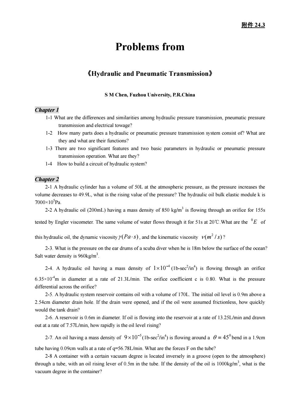
附件24.3 problem2-7 problem2-8 2-9A hydraulic pump at a flow rate of 16L/min is located under the oil surface.The oil kinematic viscosity0.1lcm/s,the oil density=80g/mthe coefficient of local resistance in the bend .and the other dimensions are shown in the figure.What is the absolute pressure at the inle port of the hydraulic pump 200 problem 2-9 problem 2-10 2-10 A type of liquid with a density of 90kg/mis flowing through a tube.Here h is 15m(see the figure) the pressures at I and 2 are 4.5x10Pa and 4x10Pa respectively.What is the flowing direction of the liquid inthe tube? 2-11 A flat is inserted into the free jet of water and vertical to the jet axes,cutting off part of the jet flow and causing the rest jet flow to swerve an angle of a.If the jet speed is=30m/s,the total flow rate=30L/s,and=12/s,what is the angle of a and the applying force F on the flat 2-12 A piston 20mm in diameter is moving downwards under a force of 150N.which forces the oil in the hydraulic cylinder out to the atmosphere through a narrow gap (.05mm)Assume the piston and the cylinder tube are set inline and the gap length is 70mm and the oil dynamic viscosity=. How long would it experience for the piston to drop down by 0.1m?
附件 24.3 problem 2-7 problem 2-8 2-9 A hydraulic pump at a flow rate of 16L/min is located under the oil surface. The oil kinematic viscosity /11.0 scm 2 ν = , the oil density , the coefficient of local resistance in the bend position 3 ρ = /880 mkg ε = 2.0 , and the other dimensions are shown in the figure. What is the absolute pressure at the inlet port of the hydraulic pump? problem 2-9 problem 2-10 2-10 A type of liquid with a density of 900kg/m3 is flowing through a tube. Here h is 15m (see the figure), the pressures at 1 and 2 are and respectively. What is the flowing direction of the liquid in the tube? Pa 5 ×105.4 Pa 5 ×10⁴ 2-11 A flat is inserted into the free jet of water and vertical to the jet axes, cutting off part of the jet flow and causing the rest jet flow to swerve an angle of α. If the jet speed is , the total flow rate , and 1 q = /30 smv = /30 sLq /12 sLq1 = , what is the angle of α and the applying force F on the flat? 2-12 A piston 20mm in diameter is moving downwards under a force of 150N, which forces the oil in the hydraulic cylinder out to the atmosphere through a narrow gap (δ=0.05mm).Assume the piston and the cylinder tube are set inline and the gap length is 70mm, and the oil dynamic viscosity . How long would it experience for the piston to drop down by 0.1m? ⋅×= sPa −3 μ 1050
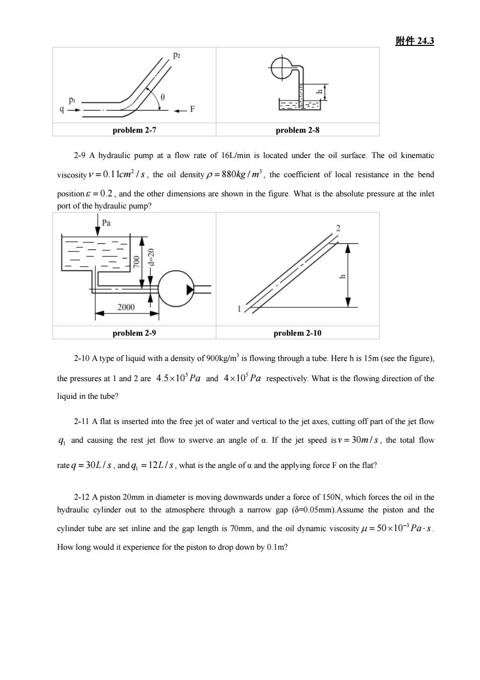
附件24.3 problem 2-11 problem 2-12 Chapter 3 3A fixed delivery 13.25L/min.The bala nce of the flow goes through a relief valve set at1.0x kPa to a reservoir at the atmospheric pressure.How much power is wasted? 3-2 In order to keep the vane in continuous contact with the cam ring in double-acting pumps,the vane slot tips usually connect with high pressure oil.This action,however,may bring about three aspects of side effects,what are they? 3-3 When selecting electric machine for pressure-limiting variable vane pumps,what kind of working conditions should we baseon for calculation 3-4 A gear pump is 48mm in the top circle diameter,24mm in gear width,and has a gear number of 14.If the highest working pressure is 10MPa,and the motor speed is 980r/min,what is the power of the motor? (volumetric efficiency of the pump=.90.the total efficiency=0.8) 3-5 An equal clearance 0.04mm exists between the two side surfaces and the gears (s=2=0.04(mm))in a gear pump.The rotating speed is 1000r/min,the output flow rate is 20L/min under a working pressure of 2.5MPa and the volumetric efficiency is 0.90.After working for a certain period. s expands to 0.042mm and s2 to 0.048mm due to friction (the other clearances were assumed to be not chans the3,=32=0.04mm) ucer requires the hydraulic motor to put out a torque of 52.5Nmd 30r/min.The hydraulic motor delivery is 12.5cmand both the volumetric and mechanical efficiencies of the hydraulic motor are09.What is the flow rate and the pressure needed? 4-2 A hydraulic motor has a delivery of 70mL/r providing an oil pressure of 10MPa and an input flow rate of 100L/min.If its volumetric and mechanical efficiencies are 09 and 0.94 respectively.and the (1)The output torque of the hydraulic motor;
附件 24.3 problem 2-11 problem 2-12 Chapter 3 3-1 A fixed delivery pump operating at 1750 r/m delivers 9.8mL/r. The load requires an average of 13.25L/min. The balance of the flow goes through a relief valve set at 1.03×10⁴ kPa to a reservoir at the atmospheric pressure. How much power is wasted? 3-2 In order to keep the vane in continuous contact with the cam ring in double-acting pumps, the vane slot tips usually connect with high pressure oil. This action, however, may bring about three aspects of side effects, what are they? 3-3 When selecting electric machine for pressure-limiting variable vane pumps, what kind of working conditions should we base on for calculation? 3-4 A gear pump is 48mm in the top circle diameter, 24mm in gear width, and has a gear number of 14. If the highest working pressure is 10MPa, and the motor speed is 980r/min, what is the power of the motor? (volumetric efficiency of the pump = 90.0 η pv , the total efficiency = 8.0 η p ) 3-5 An equal clearance 0.04mm exists between the two side surfaces and the gears ( ) in a gear pump. The rotating speed is 1000r/min, the output flow rate is 20L/min under a working pressure of 2.5MPa and the volumetric efficiency is 0.90. After working for a certain period, s )(04.0 ss 21 == mm 1 expands to 0.042mm and s2 to 0.048mm due to friction (the other clearances were assumed to be not changed). If the working pressure and the rotating speed of the pump are constant, what is the volumetric efficiency? (Reminder: the surface clearance leakage takes up 85% of the total leakage when is the )(04.0 ) ss 21 == mm Chapter 4 4-1 A speed reducer requires the hydraulic motor to put out a torque of 52.5N.m and a rotating speed of 30r/min. The hydraulic motor delivery is 12.5cm3 /r, and both the volumetric and mechanical efficiencies of the hydraulic motor are 0.9. What is the flow rate and the pressure needed? 4-2 A hydraulic motor has a delivery of 70mL/r, providing an oil pressure of 10MPa and an input flow rate of 100L/min.If its volumetric and mechanical efficiencies are 0.92 and 0.94 respectively, and the backpressure is 0.2MPa in the return oil chamber of the hydraulic motor, calculate: (1) The output torque of the hydraulic motor;
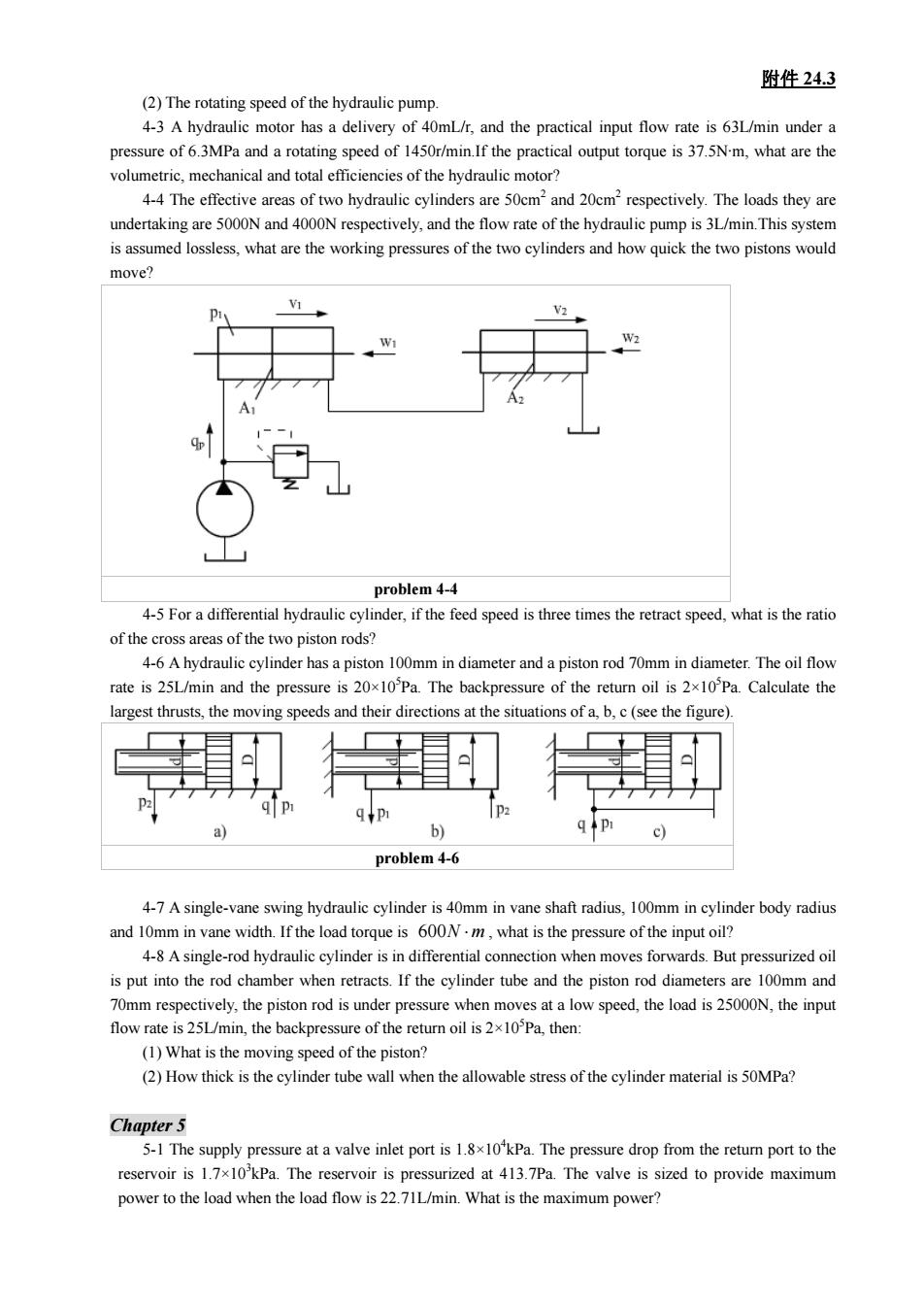
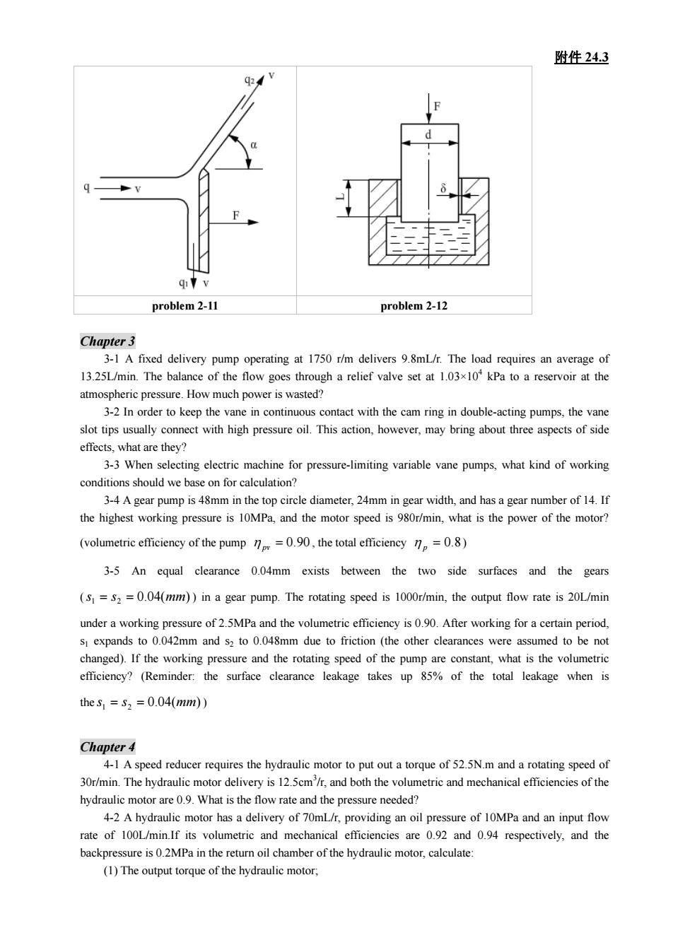
附件24.3 (2)The rotating speed of the hydraulic pump 4-3Ahydraulic motor has a delivery of the practical input flow rate is 63L/min under pressure of3MPa and a rotating speed of 1450r/min If the practical ouput torque is375Nm,what are the volumetric.mechanical and total efficiencies of the hydraulic motor? 4-4 The effective areas of two hydraulic cylinders are 50cm2and 20cm2respectively.The loads they are undertaking are 5000N and 4000N respectively,and the flow rate of the hydraulic pump is 3L/min.This system s assumed lossless.what are the working pressures of the two cylinders and how quick the two pistons would move. problem 4-4 4-5 For a differential hydraulic cylinder,if the feed speed is three times the retract speed,what is the ratio of the of the 4-6 A hydraulic cylinder has a piston 100mm in diameter and a piston rod 70mm in diameter.The oil flow rate is 25L/min and the pressure is 20x10Pa.The backpressure of the return oil is 2x10Pa Calculate the argest thrusts,the moving speeds and their directions at the situations of a,b.c (see the figure). b 1D1 problem4-6 4-7A single-vane swing hydraulic cylinder is 40mm in vane shaft radius,100mm in cylinder body radius and 10mm in vane width.If the load torque is 600N-m,what is the pressure of the input oil? 4-8 A single-rod hydraulic cylinder is in differential connection when moves forwards.But pressurized oil flow rate is 251/min,the backpressure of the retur oi,then (1)What is the moving speed of the piston? (2)How thick is the cylinder tube wall when the allowable stress of the cylinder material is 50MPa? Chapter 5 5-1The supply pressure at a valve inlet port.The pressure drop from the retum por to the reservoir is 1.7x10'kPa.The reservoir is pressurized at 413.7Pa.The valve is sized to provide maximum power to the load when the load flow is 22.71L/min.What is the maximum power?
附件 24.3 (2) The rotating speed of the hydraulic pump. 4-3 A hydraulic motor has a delivery of 40mL/r, and the practical input flow rate is 63L/min under a pressure of 6.3MPa and a rotating speed of 1450r/min.If the practical output torque is 37.5N·m, what are the volumetric, mechanical and total efficiencies of the hydraulic motor? 4-4 The effective areas of two hydraulic cylinders are 50cm2 and 20cm2 respectively. The loads they are undertaking are 5000N and 4000N respectively, and the flow rate of the hydraulic pump is 3L/min.This system is assumed lossless, what are the working pressures of the two cylinders and how quick the two pistons would move? problem 4-4 4-5 For a differential hydraulic cylinder, if the feed speed is three times the retract speed, what is the ratio of the cross areas of the two piston rods? 4-6 A hydraulic cylinder has a piston 100mm in diameter and a piston rod 70mm in diameter. The oil flow rate is 25L/min and the pressure is 20×105 Pa. The backpressure of the return oil is 2×10⁵ Pa. Calculate the largest thrusts, the moving speeds and their directions at the situations of a, b, c (see the figure). problem 4-6 4-7 A single-vane swing hydraulic cylinder is 40mm in vane shaft radius, 100mm in cylinder body radius and 10mm in vane width. If the load torque is 600 ⋅mN , what is the pressure of the input oil? 4-8 A single-rod hydraulic cylinder is in differential connection when moves forwards. But pressurized oil is put into the rod chamber when retracts. If the cylinder tube and the piston rod diameters are 100mm and 70mm respectively, the piston rod is under pressure when moves at a low speed, the load is 25000N, the input flow rate is 25L/min, the backpressure of the return oil is 2×10⁵ Pa, then: (1) What is the moving speed of the piston? (2) How thick is the cylinder tube wall when the allowable stress of the cylinder material is 50MPa? Chapter 5 5-1 The supply pressure at a valve inlet port is 1.8×10⁴ kPa. The pressure drop from the return port to the reservoir is 1.7×10³ kPa. The reservoir is pressurized at 413.7Pa. The valve is sized to provide maximum power to the load when the load flow is 22.71L/min. What is the maximum power?
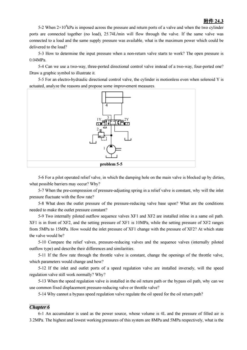
附件24.3 5-2 When 2x10'kPa is imposed across the pressure and return ports of a valve and when the two cylinder (no load),25.74L/min will flow through the valve.If the same valve was which could be delivered to the load 5-3 How to determine the input pressure when a non-return valve starts to work?The open pressure is 0.04MPa. 5-4 Can we use a two-way,three-ported directional control valve instead of a two-way,four-ported one? ti r avthe linder even when soed Y actuated,analyze the reasons and propose some improvement measures. 世☒当 = problem5-5 5-For a pilot operated relief valve,in which the damping hole on the main valve is blocked up by dirties. what possible barriers may occur?Why? 5-7 When the pre-compression of pressure-adjusting spring in a relief valve is constant,why will the inlet pressure fluctuate with the lowrate? 5-8 What does the outlet pressure of the pressure-reducing valve base upon?What are the conditions needed to make the ure c onstant? 5-9Two internally piloted outfow sequence valves XF1 and XF2 are installed inline in a same oil path XFI is in front of XF2.and the setting pressure of XFI is 10MPa.while the setting pressure of XF2 ranges from 5MPa to 15MPa.How would the inlet pressure of XFI change with the pressure of XF2?At which state the valve would be? 5-10 Compare the relief valves,pressu ing valves and the sequence valves(intemally piloted 5-11 If the flow rate through the throttle valve is constant,change the openings of the throttle valve, which parameters would change and how? 5-12 If the inlet and outlet ports of a speed regulation valve are installed inversely.will the speed regulation valve still work normally?Why? 5-13 When the speed regulation valve is installed in the o ret path or the bypass oil path,why can we use common fixed displacement pressure-reducing valve or throttle valve? 5-14 Why cannot a bypass speed regulation valve regulate the oil speed for the oil return path? Chapter 6 6-1 An is used as the power soure whose volume is 4Land the pressure of filled air is 3.2MPa.The highest and lowest working pressures of this system are 8MPa and 5MPa respectively,what is the
附件 24.3 5-2 When 2×10⁴ kPa is imposed across the pressure and return ports of a valve and when the two cylinder ports are connected together (no load), 25.74L/min will flow through the valve. If the same valve was connected to a load and the same supply pressure was available, what is the maximum power which could be delivered to the load? 5-3 How to determine the input pressure when a non-return valve starts to work? The open pressure is 0.04MPa. 5-4 Can we use a two-way, three-ported directional control valve instead of a two-way, four-ported one? Draw a graphic symbol to illustrate it. 5-5 For an electro-hydraulic directional control valve, the cylinder is motionless even when solenoid Y is actuated, analyze the reasons and propose some improvement measures. problem 5-5 5-6 For a pilot operated relief valve, in which the damping hole on the main valve is blocked up by dirties, what possible barriers may occur? Why? 5-7 When the pre-compression of pressure-adjusting spring in a relief valve is constant, why will the inlet pressure fluctuate with the flow rate? 5-8 What does the outlet pressure of the pressure-reducing valve base upon? What are the conditions needed to make the outlet pressure constant? 5-9 Two internally piloted outflow sequence valves XF1 and XF2 are installed inline in a same oil path. XF1 is in front of XF2, and the setting pressure of XF1 is 10MPa, while the setting pressure of XF2 ranges from 5MPa to 15MPa. How would the inlet pressure of XF1 change with the pressure of XF2? At which state the valve would be? 5-10 Compare the relief valves, pressure-reducing valves and the sequence valves (internally piloted outflow type) and describe their differences and similarities. 5-11 If the flow rate through the throttle valve is constant, change the openings of the throttle valve, which parameters would change and how? 5-12 If the inlet and outlet ports of a speed regulation valve are installed inversely, will the speed regulation valve still work normally? Why? 5-13 When the speed regulation valve is installed in the oil return path or the bypass oil path, why can we use common fixed displacement pressure-reducing valve or throttle valve? 5-14 Why cannot a bypass speed regulation valve regulate the oil speed for the oil return path? Chapter 6 6-1 An accumulator is used as the power source, whose volume is 4L and the pressure of filled air is 3.2MPa. The highest and lowest working pressures of this system are 8MPa and 5MPa respectively, what is the
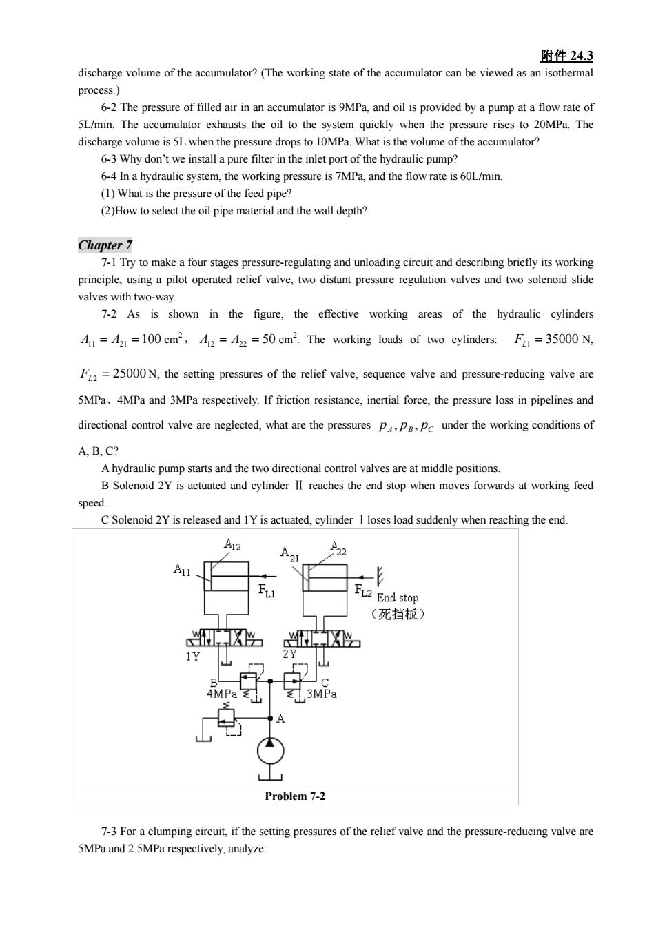
附件24.3 discharge volume of the accumulator?(The working state of the accumulator can be viewed as an isothermal process 5L/min.The accumulator exhausts the oil to the system quickly when the pressure rises to 20MPa.The discharge volume is 5L when the pressure drops to 10MPa.What is the volume of the accumulator? 6-3 Why don't we install a pure filter in the inlet port of the hydraulic pump? 6-4 Ina hydraulic system,the working pressure is 7MPa,and the flow rate is60L/min. (1)What is the pressure of the feed pipe (2)How to select the oil pipe material and the wall depth? Chapter 7 7-1Try to make a four stages pressure-reulating and unlading and describing briefly its working valves with two-way 7-2 As is shown in the figure,the effective working areas of the hydraulic cylinders A=A2 =100 cm,A2=42 =50 cm.The working loads of two cylinders:F =35000 N. F25000N,the setting pressures of the relief valve,sequence valve and pressure-reducing valve are 5MPa 4MPa and 3MPa respectively.If friction resistance,inertial force.the pressure loss in pipelines and directional control valve are neglected,what are the pressures ppp under the working conditions of A.B.C? BSolenoid 2Y is actuated and cylinder ll reaches the end stop when moves forwards at working feed speed. C Solenoid 2Y is released and 1Y is actuated,cylinder I loses load suddenly when reaching the end. A12 22 End stop (死挡板》 3MPa Problem 7-2 7-3 For a clumping circuit,if the setting pressures of the relief valve and the pressure-reducing valve are 5MPa and 2.5MPa respectively,analyze:
附件 24.3 discharge volume of the accumulator? (The working state of the accumulator can be viewed as an isothermal process.) 6-2 The pressure of filled air in an accumulator is 9MPa, and oil is provided by a pump at a flow rate of 5L/min. The accumulator exhausts the oil to the system quickly when the pressure rises to 20MPa. The discharge volume is 5L when the pressure drops to 10MPa. What is the volume of the accumulator? 6-3 Why don’t we install a pure filter in the inlet port of the hydraulic pump? 6-4 In a hydraulic system, the working pressure is 7MPa, and the flow rate is 60L/min. (1) What is the pressure of the feed pipe? (2)How to select the oil pipe material and the wall depth? Chapter 7 7-1 Try to make a four stages pressure-regulating and unloading circuit and describing briefly its working principle, using a pilot operated relief valve, two distant pressure regulation valves and two solenoid slide valves with two-way. 7-2 As is shown in the figure, the effective working areas of the hydraulic cylinders 11 AA 21 == 100 cm 2, 12 AA 22 == 50 cm 2 . The working loads of two cylinders: N, N, the setting pressures of the relief valve, sequence valve and pressure-reducing valve are 5MPa、4MPa and 3MPa respectively. If friction resistance, inertial force, the pressure loss in pipelines and directional control valve are neglected, what are the pressures under the working conditions of A, B, C? 35000 FL1 = 25000 FL2 = ppp CBA , A hydraulic pump starts and the two directional control valves are at middle positions. B Solenoid 2Y is actuated and cylinder Ⅱ reaches the end stop when moves forwards at working feed speed. C Solenoid 2Y is released and 1Y is actuated, cylinder Ⅰloses load suddenly when reaching the end. Problem 7-2 7-3 For a clumping circuit, if the setting pressures of the relief valve and the pressure-reducing valve are 5MPa and 2.5MPa respectively, analyze:
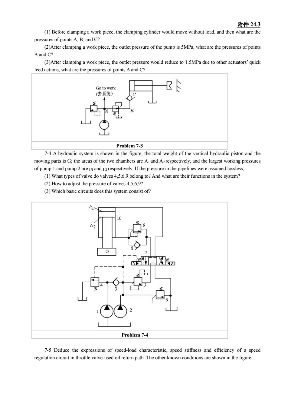
附件24.3 (1)Before clamping a work piece,the clamping cylinder would move without load,and then what are the pressures of pointsA.B.andC? ()After elampinga work piece,the outlet pressure of the pump is5MPa,what are the pressures of points A and C? (3)After clamping a work piece.the outlet pressure would reduce to 1.5MPa due to other actuators'quick feed actions,what are the pressures of points A and C? h9 Problem 7-3 7-4 A hydraulic system is shown in the figure,the total weight of the vertical hydraulic piston and the ing pressures of pump and pump2 are pand parespectively.If the pressure in the pipelines were assumed lossless (1)What types of valve do valves45,9 belong to?And what are their functions in the system? (2)How to adjust the pressure of valves 4.6,9? ()Which basic circuits does this system consist of? Problem 7-4 7-5 Deduce the expressions of speed-load characteristic,speed stiffness and efficiency of a speed regulation circuit n th ote valve-used oi retur path. The other known conditions are shown in the figure
附件 24.3 (1) Before clamping a work piece, the clamping cylinder would move without load, and then what are the pressures of points A, B, and C? (2)After clamping a work piece, the outlet pressure of the pump is 5MPa, what are the pressures of points A and C? (3)After clamping a work piece, the outlet pressure would reduce to 1.5MPa due to other actuators’ quick feed actions, what are the pressures of points A and C? Problem 7-3 7-4 A hydraulic system is shown in the figure, the total weight of the vertical hydraulic piston and the moving parts is G; the areas of the two chambers are A1 and A2 respectively, and the largest working pressures of pump 1 and pump 2 are p1 and p2 respectively. If the pressure in the pipelines were assumed lossless, (1) What types of valve do valves 4,5,6,9 belong to? And what are their functions in the system? (2) How to adjust the pressure of valves 4,5,6,9? (3) Which basic circuits does this system consist of? Problem 7-4 7-5 Deduce the expressions of speed-load characteristic, speed stiffness and efficiency of a speed regulation circuit in throttle valve-used oil return path. The other known conditions are shown in the figure
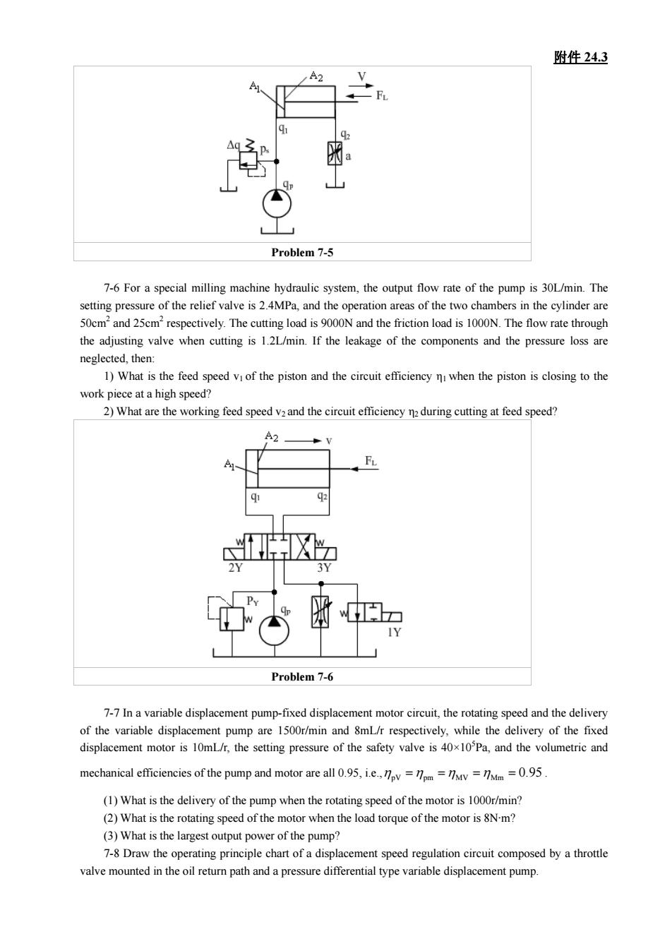
附件24.3 Problem7-5 7-For a special milling machine hydraulic system,the output flow rate of the pump is 30L/min.The setting pressure of the relief valve is 2.4MPa,and the operation areas of the two chambers in the cylinder are 50cm2and 25cm2respectively.The cutting load is 9000N and the friction load is 1000N.The flow rate through the adiusting valve when cutting is 1.21/min.If the leakage of the components and the pressure loss are neglected,then 1)What is the feed speed of the piston and the circuit the piston is closing to the work piece at a high speed? 2)What are the working feed speed v2and the circuit efficiency n during cutting at feed speed? X Problem 7-6 7-7Ina variable displacemen pump-fixed speed and the delive of the variable disolacement mototoingthPand the oie e the d ivery mechanical efficiencies of the pump and motor are all 95.ie====0.95 (1)What is the delivery of the pump when the rotating speed of the motor is 1000r/min? (2)What is the rotating speed of the motor when the od orque of the motor ism? (3)What is the largest ouput power of the pump? 7-8 Draw the operating principle chart of a displacement speed regulation circuit composed by a throttle valve mounted in the oil return path and a pressure differential type variable displacement pump
附件 24.3 Problem 7-5 7-6 For a special milling machine hydraulic system, the output flow rate of the pump is 30L/min. The setting pressure of the relief valve is 2.4MPa, and the operation areas of the two chambers in the cylinder are 50cm2 and 25cm2 respectively. The cutting load is 9000N and the friction load is 1000N. The flow rate through the adjusting valve when cutting is 1.2L/min. If the leakage of the components and the pressure loss are neglected, then: 1) What is the feed speed v1 of the piston and the circuit efficiency η1 when the piston is closing to the work piece at a high speed? 2) What are the working feed speed v2 and the circuit efficiency η2 during cutting at feed speed? Problem 7-6 7-7 In a variable displacement pump-fixed displacement motor circuit, the rotating speed and the delivery of the variable displacement pump are 1500r/min and 8mL/r respectively, while the delivery of the fixed displacement motor is 10mL/r, the setting pressure of the safety valve is 40×105 Pa, and the volumetric and mechanical efficiencies of the pump and motor are all 0.95, i.e., MV Mm 0.95 ηpV =ηpm =η =η = . (1) What is the delivery of the pump when the rotating speed of the motor is 1000r/min? (2) What is the rotating speed of the motor when the load torque of the motor is 8N·m? (3) What is the largest output power of the pump? 7-8 Draw the operating principle chart of a displacement speed regulation circuit composed by a throttle valve mounted in the oil return path and a pressure differential type variable displacement pump
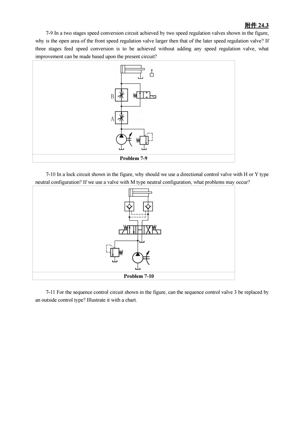
附件24.3 7-9 In a two stages speed conversion circuit achieved by two speed regulation valves shown in the figure. why is the open rea of the front speed regulation valve larger then that of the aterspeed regulation valve?If three stages feed speed conversion is to be achieved without adding any speed regulation valve,what improvement can be made based upon the present circuit? 子8 为 用 中 Problem 7-9 7-10 Ina lock circuit shown in the figure,why should we use a directional control valve with Hor Y type neutral configuration?If we use a valve with M type neutral configuration,what problems may occur? ☒ 山 Problem 7-10 7-11 For the sequence control circuit shown in the figure,can the sequence contro valve3 be replaced by an outside control type?Illustrate it with a chart
附件 24.3 7-9 In a two stages speed conversion circuit achieved by two speed regulation valves shown in the figure, why is the open area of the front speed regulation valve larger then that of the later speed regulation valve? If three stages feed speed conversion is to be achieved without adding any speed regulation valve, what improvement can be made based upon the present circuit? Problem 7-9 7-10 In a lock circuit shown in the figure, why should we use a directional control valve with H or Y type neutral configuration? If we use a valve with M type neutral configuration, what problems may occur? Problem 7-10 7-11 For the sequence control circuit shown in the figure, can the sequence control valve 3 be replaced by an outside control type? Illustrate it with a chart
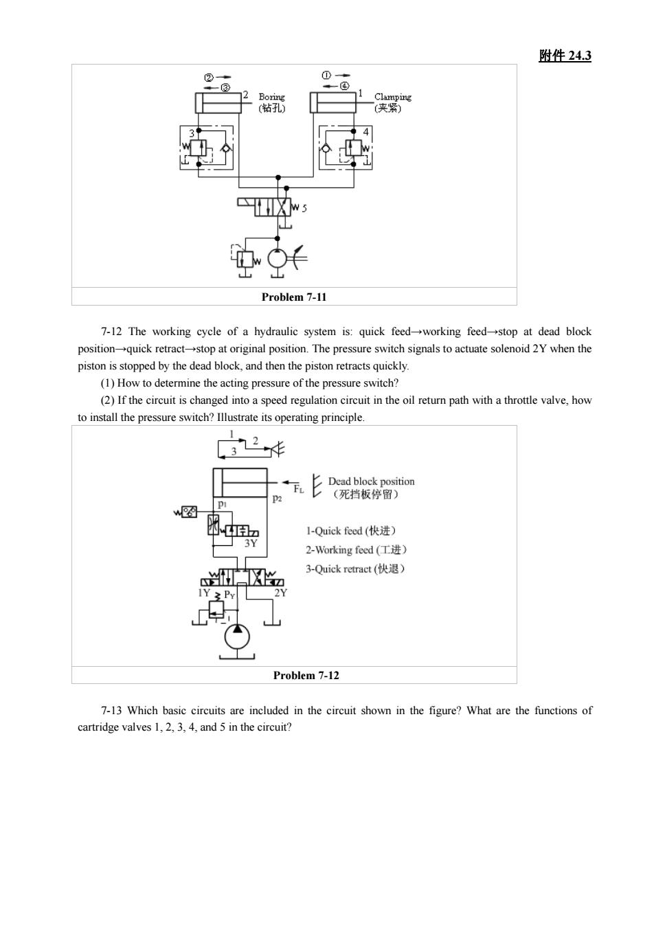
附件24.3 的wO卡 Problem 7-11 7-12 The working cycle of a hydraulic system is:quick feed-working feed-stop at dead block position →quick retra tion.The pressure switch ptisstppd byte d nd then the pon retets u actuate solenoid 2Y when the (1)How to determine the acting pressure of the pressure switch? (2)If the circuit is changed into a speed regulation circuit in the oil retur path with a throttle valve,how to install the pressure switch?Illustrate its operating principle. 2 死指板停 w图 l-Quick feed(快进 2-Working feed(工进) 3-Quick retract(快退) 3 P Problem7-12 7-13 Which circuits are inluded in the circuit shown in the figure?What are the functions of cartridge valves 1,2,3,4,and 5 in the circuit
附件 24.3 Problem 7-11 7-12 The working cycle of a hydraulic system is: quick feed→working feed→stop at dead block position→quick retract→stop at original position. The pressure switch signals to actuate solenoid 2Y when the piston is stopped by the dead block, and then the piston retracts quickly. (1) How to determine the acting pressure of the pressure switch? (2) If the circuit is changed into a speed regulation circuit in the oil return path with a throttle valve, how to install the pressure switch? Illustrate its operating principle. Problem 7-12 7-13 Which basic circuits are included in the circuit shown in the figure? What are the functions of cartridge valves 1, 2, 3, 4, and 5 in the circuit?