正在加载图片...
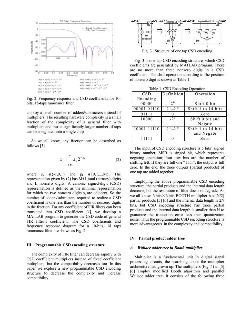
…品 Fig.3.Structure of one tap CSD encoding Fig.3 is one tap CSD encoding structure,which CSD coefficients are generated by MATLAB program.There are no more than three nonzero digits in a CSD coefficient.The shift operation according to the position of nonzero digit is shown as Table 1. 物票)·-3" 力45与。2·】请 侧)=9+++-34 00年2+1…2+ Table 1.CSD Encoding Operation CSD Definition Operation Fig.2.Frequency response and CSD coefficients for 10- Encoding bits,18-taps luminance filter 00000 2 Shift 0 bit 00001-01110 21214 Shift 1 to 14 bits employ a small number of adders/subtracters instead of 01111 0 Zero multipliers.The resulting hardware complexity is a small 10000 -2 Shift 0 bit and fraction of the complexity of a general filter with Negate multipliers and thus a significantly larger number of taps 10001-11110 2124 Shift 1 to 14 bits can be integrated into a single chip. and Negate As we all know,any fraction can be described as 11111 0 Zero follows [3]. The input of CSD encoding structure is 5 bits'signed binary number.MSB is singed bit,which represents X=S2-P (2) negating operation;four low bits are the number of K= shifting left.If they are full one"1111",the output is full zero.In the end,the three outputs (partial products)of where sk∈{-l,0,l}and pk∈{0,l,,M.The one tap are added together. representation given by (2)has M+1 total (ternary)digits and L nonzero digits.A canonic signed-digit (CSD) Employing the above programmable CSD encoding representation is defined as the minimal representation structure,the partial products and the internal data length for which no two nonzero digits sy are adjacent.So the decrease,but the resolution of filter does not degrade.As number of adders/subtracters required to realize a CSD we all know,Nbits X Nbits BOOTH multiplier has [N/2] coefficient is one less than the number of nonzero digits partial products [5][6]and the internal data length is 2N in the fraction.For any coefficient of FIR filters can been bits,but CSD encoding structure has three partial translated into CSD coefficient [4],we develop a products and the internal data length is smaller than N to MATLAB program to generate the CSD code of general guarantee the truncation error less than quantization FIR filter's coefficient.The CSD coefficients and noise.Thus the programmable CSD encoding structure is frequency response diagram for a 10-bits,18 taps more advantageous in the complexity and compatibility. luminance filter are shown as Fig.2. IV.Partial product adder tree III.Programmable CSD encoding structure A. Wallace adder tree in Booth multiplier The complexity of FIR filter can decrease rapidly with CSD coefficient multipliers instead of fixed coefficient Multiplier is a fundamental unit in digital signal multipliers,but the compatibility decreases too.In this processing circuits,the searching about the multiplier paper we explore a new programmable CSD encoding architecture had grown up.The multipliers(Fig.4)in [5] structure to decrease the complexity and increase [6]employ modified Booth algorithm and parallel compatibility. Wallace adder tree.It consists of the following threeFig. 2. Frequency response and CSD coefficients for 10- bits, 18-taps luminance filter employ a small number of adders/subtracters instead of multipliers. The resulting hardware complexity is a small fraction of the complexity of a general filter with multipliers and thus a significantly larger number of taps can be integrated into a single chip. As we all know, any fraction can be described as follows [3]. = − = L K p k k x s 1 2 (2) where sk ∈{-1,0,1} and pk ∈{0,1,...,M}. The representation given by (2) has M+1 total (ternary) digits and L nonzero digits. A canonic signed-digit (CSD) representation is defined as the minimal representation for which no two nonzero digits sk are adjacent. So the number of adders/subtracters required to realize a CSD coefficient is one less than the number of nonzero digits in the fraction. For any coefficient of FIR filters can been translated into CSD coefficient [4], we develop a MATLAB program to generate the CSD code of general FIR filter’s coefficient. The CSD coefficients and frequency response diagram for a 10-bits, 18 taps luminance filter are shown as Fig. 2. III. Programmable CSD encoding structure The complexity of FIR filter can decrease rapidly with CSD coefficient multipliers instead of fixed coefficient multipliers, but the compatibility decreases too. In this paper we explore a new programmable CSD encoding structure to decrease the complexity and increase compatibility. D Fixed CSD TAP 8 2 − − 10 2 − 0 h(0) D h(0) CSD coefficient D Programmable CSD TAP h(0) 5 11000 5 01010 5 11111 xin(i-1) xin(i) xin(i-1) xin(i) xin(i-1) xin(i) xin(i-1) xin(i-1) xin(i) xin(i-1) xin(i) Fig. 3. Structure of one tap CSD encoding Fig. 3 is one tap CSD encoding structure, which CSD coefficients are generated by MATLAB program. There are no more than three nonzero digits in a CSD coefficient. The shift operation according to the position of nonzero digit is shown as Table 1. Table 1. CSD Encoding Operation CSD Encoding Definition Operation 00000 20 Shift 0 bit 00001-01110 2- 1∼2-14 Shift 1 to 14 bits 01111 0 Zero 10000 -20 Shift 0 bit and Negate 10001-11110 2- 1∼2-14 Shift 1 to 14 bits and Negate 11111 0 Zero The input of CSD encoding structure is 5 bits’ signed binary number. MSB is singed bit, which represents negating operation; four low bits are the number of shifting left. If they are full one “1111”, the output is full zero. In the end, the three outputs (partial products) of one tap are added together. Employing the above programmable CSD encoding structure, the partial products and the internal data length decrease, but the resolution of filter does not degrade. As we all know, Nbits×Nbits BOOTH multiplier has [N/2] partial products [5] [6] and the internal data length is 2N bits, but CSD encoding structure has three partial products and the internal data length is smaller than N to guarantee the truncation error less than quantization noise. Thus the programmable CSD encoding structure is more advantageous in the complexity and compatibility. IV. Partial product adder tree A. Wallace adder tree in Booth multiplier Multiplier is a fundamental unit in digital signal processing circuits, the searching about the multiplier architecture had grown up. The multipliers (Fig. 4) in [5] [6] employ modified Booth algorithm and parallel Wallace adder tree. It consists of the following three