正在加载图片...

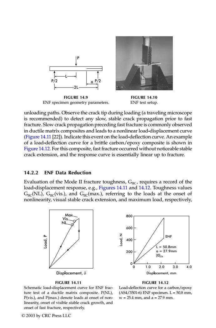
P/2 FIGURE 14.9 FIGURE 14.10 ENF specimen geometry parameters. ENF test setup. unloading paths.Observe the crack tip during loading(a traveling microscope is recommended)to detect any slow,stable crack propagation prior to fast fracture.Slow crack propagation preceding fast fracture is commonly observed in ductile matrix composites and leads to a nonlinear load-displacement curve (Figure 14.11 [22]).Indicate this event on the load-deflection curve.An example of a load-deflection curve for a brittle carbon/epoxy composite is shown in Figure 14.12.For this composite,fast fracture occurred without noticeable stable crack extension,and the response curve is essentially linear up to fracture. 14.2.2 ENF Data Reduction Evaluation of the Mode II fracture toughness,Guc,requires a record of the load-displacement response,e.g.,Figures 14.11 and 14.12.Toughness values Guc(NL),Guc(vis.),and Guc(max.),referring to the loads at the onset of nonlinearity,visual stable crack extension,and maximum load,respectively, Max 800 VIS 600 Z ENF 400 L=50.8mm 200 a=27.9mm [0124 0 1.0 2.03.0 4.0 Displacement,8 Displacement,mm FIGURE 14.11 FIGURE 14.12 Schematic load-displacement curve for ENF frac- Load-deflection curve for a carbon/epoxy ture test of a ductile matrix composite.P(NL), (AS4/3501-6)ENF specimen.L=50.8 mm, P(vis.),and P(max.)denote loads at onset of non- w =25.4 mm,and a =27.9 mm. linearity,onset of visible stable crack growth,and onset of fast fracture,respectively. ©2003 by CRC Press LLCunloading paths. Observe the crack tip during loading (a traveling microscope is recommended) to detect any slow, stable crack propagation prior to fast fracture. Slow crack propagation preceding fast fracture is commonly observed in ductile matrix composites and leads to a nonlinear load-displacement curve (Figure 14.11 [22]). Indicate this event on the load-deflection curve.An example of a load-deflection curve for a brittle carbon/epoxy composite is shown in Figure 14.12. For this composite, fast fracture occurred without noticeable stable crack extension, and the response curve is essentially linear up to fracture. 14.2.2 ENF Data Reduction Evaluation of the Mode II fracture toughness, GIIC , requires a record of the load-displacement response, e.g., Figures 14.11 and 14.12. Toughness values GIIC(NL), GIIC(vis.), and GIIC(max.), referring to the loads at the onset of nonlinearity, visual stable crack extension, and maximum load, respectively, FIGURE 14.9 ENF specimen geometry parameters. FIGURE 14.10 ENF test setup. FIGURE 14.11 Schematic load-displacement curve for ENF fracture test of a ductile matrix composite. P(NL), P(vis.), and P(max.) denote loads at onset of nonlinearity, onset of visible stable crack growth, and onset of fast fracture, respectively. FIGURE 14.12 Load-deflection curve for a carbon/epoxy (AS4/3501-6) ENF specimen. L = 50.8 mm, w = 25.4 mm, and a = 27.9 mm. TX001_ch14_Frame Page 194 Saturday, September 21, 2002 5:09 AM © 2003 by CRC Press LLC