正在加载图片...

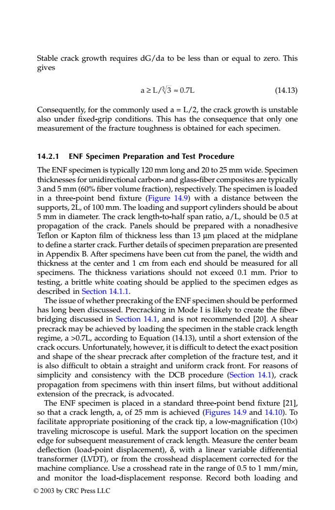
Stable crack growth requires dG/da to be less than or equal to zero.This gives a≥L//3≈0.7L (14.13) Consequently,for the commonly used a =L/2,the crack growth is unstable also under fixed-grip conditions.This has the consequence that only one measurement of the fracture toughness is obtained for each specimen. 14.2.1 ENF Specimen Preparation and Test Procedure The ENF specimen is typically 120 mm long and 20 to 25 mm wide.Specimen thicknesses for unidirectional carbon-and glass-fiber composites are typically 3 and 5 mm(60%fiber volume fraction),respectively.The specimen is loaded in a three-point bend fixture (Figure 14.9)with a distance between the supports,2L,of 100 mm.The loading and support cylinders should be about 5 mm in diameter.The crack length-to-half span ratio,a/L,should be 0.5 at propagation of the crack.Panels should be prepared with a nonadhesive Teflon or Kapton film of thickness less than 13 um placed at the midplane to define a starter crack.Further details of specimen preparation are presented in Appendix B.After specimens have been cut from the panel,the width and thickness at the center and 1 cm from each end should be measured for all specimens.The thickness variations should not exceed 0.1 mm.Prior to testing,a brittle white coating should be applied to the specimen edges as described in Section 14.1.1. The issue of whether precraking of the ENF specimen should be performed has long been discussed.Precracking in Mode I is likely to create the fiber- bridging discussed in Section 14.1,and is not recommended [20].A shear precrack may be achieved by loading the specimen in the stable crack length regime,a >0.7L,according to Equation (14.13),until a short extension of the crack occurs.Unfortunately,however,it is difficult to detect the exact position and shape of the shear precrack after completion of the fracture test,and it is also difficult to obtain a straight and uniform crack front.For reasons of simplicity and consistency with the DCB procedure (Section 14.1),crack propagation from specimens with thin insert films,but without additional extension of the precrack,is advocated. The ENF specimen is placed in a standard three-point bend fixture [21], so that a crack length,a,of 25 mm is achieved(Figures 14.9 and 14.10).To facilitate appropriate positioning of the crack tip,a low-magnification(10x) traveling microscope is useful.Mark the support location on the specimen edge for subsequent measurement of crack length.Measure the center beam deflection (load-point displacement),6,with a linear variable differential transformer(LVDT),or from the crosshead displacement corrected for the machine compliance.Use a crosshead rate in the range of 0.5 to 1 mm/min, and monitor the load-displacement response.Record both loading and 2003 by CRC Press LLCStable crack growth requires dG/da to be less than or equal to zero. This gives (14.13) Consequently, for the commonly used a = L/2, the crack growth is unstable also under fixed-grip conditions. This has the consequence that only one measurement of the fracture toughness is obtained for each specimen. 14.2.1 ENF Specimen Preparation and Test Procedure The ENF specimen is typically 120 mm long and 20 to 25 mm wide. Specimen thicknesses for unidirectional carbon- and glass-fiber composites are typically 3 and 5 mm (60% fiber volume fraction), respectively. The specimen is loaded in a three-point bend fixture (Figure 14.9) with a distance between the supports, 2L, of 100 mm. The loading and support cylinders should be about 5 mm in diameter. The crack length-to-half span ratio, a/L, should be 0.5 at propagation of the crack. Panels should be prepared with a nonadhesive Teflon or Kapton film of thickness less than 13 µm placed at the midplane to define a starter crack. Further details of specimen preparation are presented in Appendix B. After specimens have been cut from the panel, the width and thickness at the center and 1 cm from each end should be measured for all specimens. The thickness variations should not exceed 0.1 mm. Prior to testing, a brittle white coating should be applied to the specimen edges as described in Section 14.1.1. The issue of whether precraking of the ENF specimen should be performed has long been discussed. Precracking in Mode I is likely to create the fiberbridging discussed in Section 14.1, and is not recommended [20]. A shear precrack may be achieved by loading the specimen in the stable crack length regime, a >0.7L, according to Equation (14.13), until a short extension of the crack occurs. Unfortunately, however, it is difficult to detect the exact position and shape of the shear precrack after completion of the fracture test, and it is also difficult to obtain a straight and uniform crack front. For reasons of simplicity and consistency with the DCB procedure (Section 14.1), crack propagation from specimens with thin insert films, but without additional extension of the precrack, is advocated. The ENF specimen is placed in a standard three-point bend fixture [21], so that a crack length, a, of 25 mm is achieved (Figures 14.9 and 14.10). To facilitate appropriate positioning of the crack tip, a low-magnification (10×) traveling microscope is useful. Mark the support location on the specimen edge for subsequent measurement of crack length. Measure the center beam deflection (load-point displacement), δ, with a linear variable differential transformer (LVDT), or from the crosshead displacement corrected for the machine compliance. Use a crosshead rate in the range of 0.5 to 1 mm/min, and monitor the load-displacement response. Record both loading and a L/ 0.7L ≥ ≈ 3 3 TX001_ch14_Frame Page 193 Saturday, September 21, 2002 5:09 AM © 2003 by CRC Press LLC