正在加载图片...

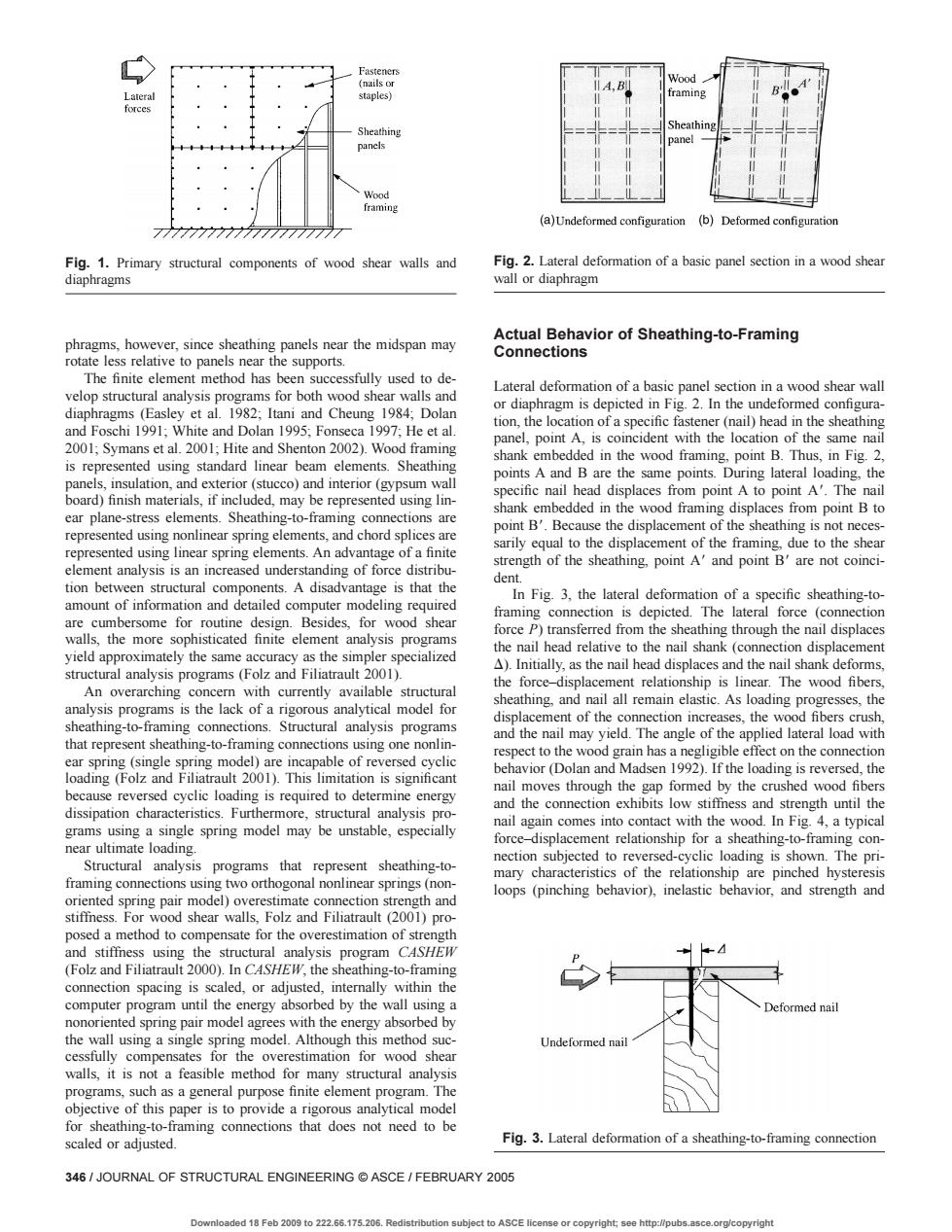
(a)Undeformed r(b)Deformedngurio Fig1.Primary structural components of wood shear walls and diaphragms phragms.sheathing panels near the midspan may rohng-to-raming The finite element method has been successfully used to de elop structu od she Lateral defor and Foschi White and Dolan 9 Fonseca He eta n6ow曲e8ec panel. e sa 00 Symans et al.0 Hite and Shenton 2002). points A and B are the same points.During latera lo the 的 om point A to point A' point BBecause the displacement of the sheathing is not ne pre e is that the dent amountofinformatoi iled comput elem ent an nail shank currently ilable structura he nalytical mode thing,and n oI a all remain elastic.As loading pro and the nail may yield.The angle of the applied late 0D This limi eversed cyclic loading is required to determine energy nail moves through the gap formed by the crus diss the low the force ment relationship for a sheathing-t con programs that nec e pr represent sheat ing-to relationsh t and loops (pinching behavior).inelastic behavior,and strength and mation of s isscaled,or adjusted ed by the wall using a mo es for the ove estimation for wood shea scaled Fig.3.Lateral deformation of a sheathing-to-framing connection 346/JOURNAL OF STRUCTURAL ENGINEERING ASCE/FEBRUARY 2005 Downloadod 18 Fob 2009 to 222.66.175.206.Redi o ASCE co.org/copyright phragms, however, since sheathing panels near the midspan may rotate less relative to panels near the supports. The finite element method has been successfully used to develop structural analysis programs for both wood shear walls and diaphragms (Easley et al. 1982; Itani and Cheung 1984; Dolan and Foschi 1991; White and Dolan 1995; Fonseca 1997; He et al. 2001; Symans et al. 2001; Hite and Shenton 2002). Wood framing is represented using standard linear beam elements. Sheathing panels, insulation, and exterior (stucco) and interior (gypsum wall board) finish materials, if included, may be represented using linear plane-stress elements. Sheathing-to-framing connections are represented using nonlinear spring elements, and chord splices are represented using linear spring elements. An advantage of a finite element analysis is an increased understanding of force distribution between structural components. A disadvantage is that the amount of information and detailed computer modeling required are cumbersome for routine design. Besides, for wood shear walls, the more sophisticated finite element analysis programs yield approximately the same accuracy as the simpler specialized structural analysis programs (Folz and Filiatrault 2001). An overarching concern with currently available structural analysis programs is the lack of a rigorous analytical model for sheathing-to-framing connections. Structural analysis programs that represent sheathing-to-framing connections using one nonlinear spring (single spring model) are incapable of reversed cyclic loading (Folz and Filiatrault 2001). This limitation is significant because reversed cyclic loading is required to determine energy dissipation characteristics. Furthermore, structural analysis programs using a single spring model may be unstable, especially near ultimate loading. Structural analysis programs that represent sheathing-toframing connections using two orthogonal nonlinear springs (nonoriented spring pair model) overestimate connection strength and stiffness. For wood shear walls, Folz and Filiatrault (2001) proposed a method to compensate for the overestimation of strength and stiffness using the structural analysis program CASHEW (Folz and Filiatrault 2000). In CASHEW, the sheathing-to-framing connection spacing is scaled, or adjusted, internally within the computer program until the energy absorbed by the wall using a nonoriented spring pair model agrees with the energy absorbed by the wall using a single spring model. Although this method successfully compensates for the overestimation for wood shear walls, it is not a feasible method for many structural analysis programs, such as a general purpose finite element program. The objective of this paper is to provide a rigorous analytical model for sheathing-to-framing connections that does not need to be scaled or adjusted. Actual Behavior of Sheathing-to-Framing Connections Lateral deformation of a basic panel section in a wood shear wall or diaphragm is depicted in Fig. 2. In the undeformed configuration, the location of a specific fastener (nail) head in the sheathing panel, point A, is coincident with the location of the same nail shank embedded in the wood framing, point B. Thus, in Fig. 2, points A and B are the same points. During lateral loading, the specific nail head displaces from point A to point A8. The nail shank embedded in the wood framing displaces from point B to point B8. Because the displacement of the sheathing is not necessarily equal to the displacement of the framing, due to the shear strength of the sheathing, point A8 and point B8 are not coincident. In Fig. 3, the lateral deformation of a specific sheathing-toframing connection is depicted. The lateral force (connection force P) transferred from the sheathing through the nail displaces the nail head relative to the nail shank (connection displacement D). Initially, as the nail head displaces and the nail shank deforms, the force–displacement relationship is linear. The wood fibers, sheathing, and nail all remain elastic. As loading progresses, the displacement of the connection increases, the wood fibers crush, and the nail may yield. The angle of the applied lateral load with respect to the wood grain has a negligible effect on the connection behavior (Dolan and Madsen 1992). If the loading is reversed, the nail moves through the gap formed by the crushed wood fibers and the connection exhibits low stiffness and strength until the nail again comes into contact with the wood. In Fig. 4, a typical force–displacement relationship for a sheathing-to-framing connection subjected to reversed-cyclic loading is shown. The primary characteristics of the relationship are pinched hysteresis loops (pinching behavior), inelastic behavior, and strength and Fig. 1. Primary structural components of wood shear walls and diaphragms Fig. 2. Lateral deformation of a basic panel section in a wood shear wall or diaphragm Fig. 3. Lateral deformation of a sheathing-to-framing connection 346 / JOURNAL OF STRUCTURAL ENGINEERING © ASCE / FEBRUARY 2005 Downloaded 18 Feb 2009 to 222.66.175.206. Redistribution subject to ASCE license or copyright; see http://pubs.asce.org/copyright