正在加载图片...

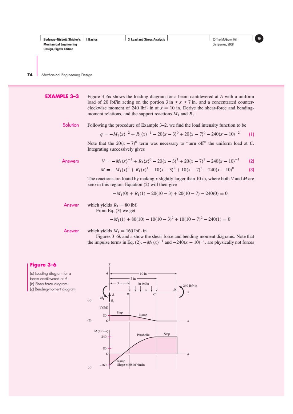
Budynas-Nisbett:Shigley's I.Basics 3.Load and Stress Analysis T©The McGraw-Hill Mechanical Engineering Companies,2008 Design,Eighth Edition 74 I Mechanical Engineering Design EXAMPLE 3-3 Figure 3-6a shows the loading diagram for a beam cantilevered at A with a uniform load of 20 Ibf/in acting on the portion 3 in sxs7 in,and a concentrated counter- clockwise moment of 240 lbf.in at x=10 in.Derive the shear-force and bending- moment relations,and the support reactions Mi and R1. Solution Following the procedure of Example 3-2,we find the load intensity function to be q=-M1x-2+R1x)-1-20x-3)°+20x-7)°-240(x-10)-2(1 Note that the 20(x-7)0 term was necessary to"turn off"the uniform load at C. Integrating successively gives Answers V=-M1x)-1+R1(x)°-20x-3)1+20x-7)1-240-10-21 M=-M1(x)°+R1x)1-10-3)2+10x-7)2-240G-10)0 (3) The reactions are found by makingx slightly larger than 10 in,where both Vand M are zero in this region.Equation(2)will then give -M1(0)+R1(1)-20(10-3)+20(10-7)-240(0)=0 Answer which yields R=80 Ibf. From Eq.(3)we get -M1(1)+80(10)-10(10-3)2+10(10-7)2-240(1)=0 Answer which yields M=160 Ibf.in. Figures 3-6b and c show the shear-force and bending-moment diagrams.Note that the impulse terms in Eq.(2).-M(x)and-240(x-10)1,are physically not forces Figure 3-6 (a)Loading diagram for a beam cantilevered at A. 7 in (b)Shear-force diagram. 3in- 240 lbf-in (c)Bending-moment diagram. (a) V(Ibf) Step Ramp (b) M(Ibf-in) Step 240 Parabolic 80- Ramp 160 Slope=80 Ibf-in/inBudynas−Nisbett: Shigley’s Mechanical Engineering Design, Eighth Edition I. Basics 3. Load and Stress Analysis © The McGraw−Hill 79 Companies, 2008 74 Mechanical Engineering Design EXAMPLE 3–3 Figure 3–6a shows the loading diagram for a beam cantilevered at A with a uniform load of 20 lbf/in acting on the portion 3 in ≤ x ≤ 7 in, and a concentrated counterclockwise moment of 240 lbf · in at x = 10 in. Derive the shear-force and bendingmoment relations, and the support reactions M1 and R1. Solution Following the procedure of Example 3–2, we find the load intensity function to be q = −M1x −2 + R1x −1 − 20x − 3 0 + 20x − 7 0 − 240x − 10 −2 (1) Note that the 20x − 70 term was necessary to “turn off” the uniform load at C. Integrating successively gives Answers V = −M1x −1 + R1x 0 − 20x − 3 1 + 20x − 7 1 − 240x − 10 −1 (2) M = −M1x 0 + R1x 1 − 10x − 3 2 + 10x − 7 2 − 240x − 10 0 (3) The reactions are found by making x slightly larger than 10 in, where both V and M are zero in this region. Equation (2) will then give −M1(0) + R1(1) − 20(10 − 3) + 20(10 − 7) − 240(0) = 0 Answer which yields R1 = 80 lbf. From Eq. (3) we get −M1(1) + 80(10) − 10(10 − 3) 2 + 10(10 − 7) 2 − 240(1) = 0 Answer which yields M1 = 160 lbf · in. Figures 3–6b and c show the shear-force and bending-moment diagrams. Note that the impulse terms in Eq. (2), −M1x−1 and −240x − 10−1, are physically not forces (a) (b) D A B C y q x 10 in 7 in 3 in R1 M1 20 lbf/in 240 lbfin x V (lbf) O Step Ramp (c) x M (lbfin) O –160 80 Parabolic Step 80 240 Ramp Slope = 80 lbfin/in Figure 3–6 (a) Loading diagram for a beam cantilevered at A. (b) Shear-force diagram. (c) Bending-moment diagram.���������������������������������������