正在加载图片...

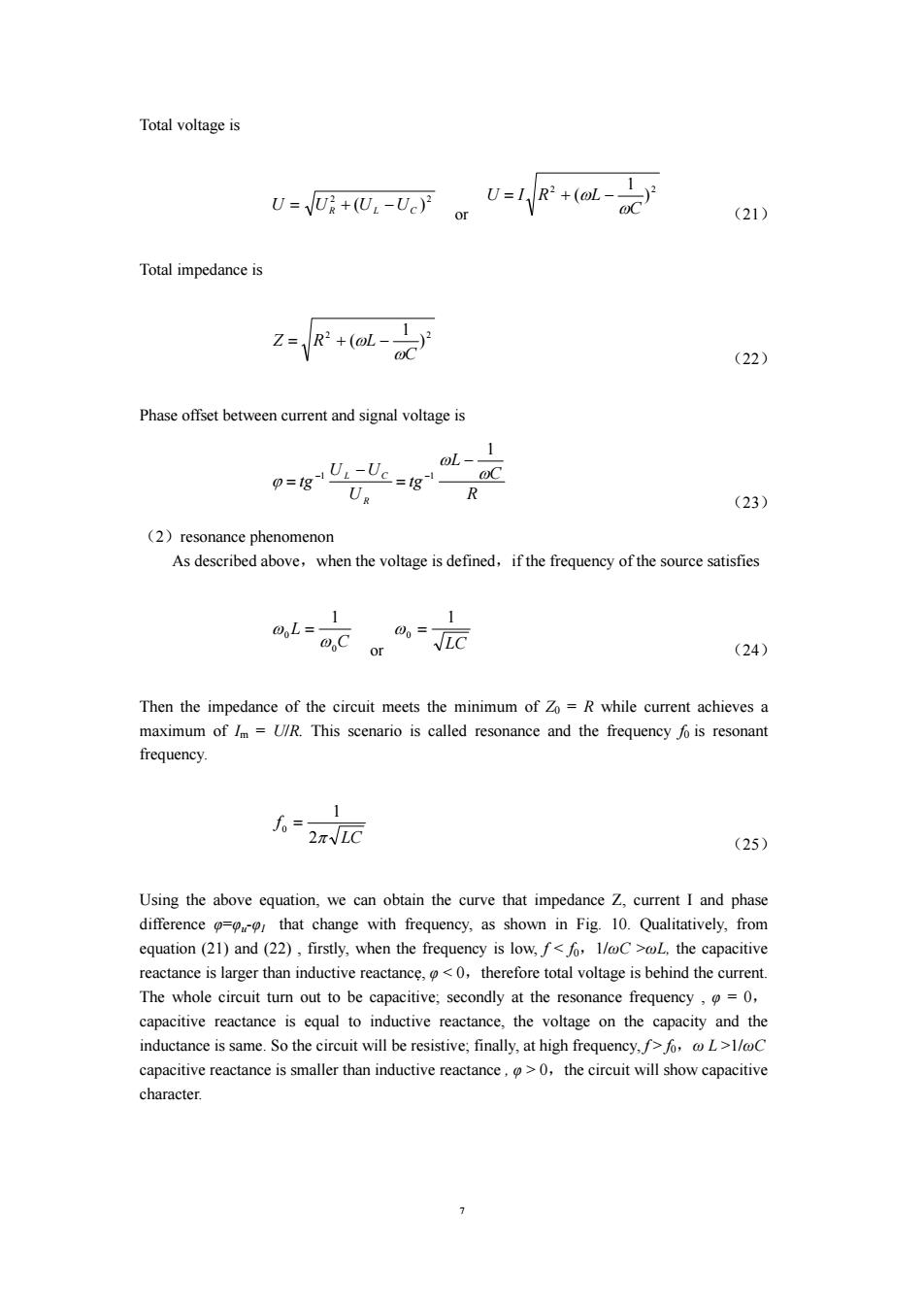
Total voltage is U--Vo)+(oL-oc (21) Total impedance is +a Z1 (22) Phase offset between current and signal voltage is 0L、1 UUc=OC UR R (23) (2)resonance phenomenon As described above,when the voltage is defined,if the frequency of the source satisfies 1 1 0L= C 00= or (24) Then the impedance of the circuit meets the minimum of Zo =R while current achieves a maximum of /m =U/R.This scenario is called resonance and the frequency fo is resonant frequency. 1 0=。 2πVLC (25) Using the above equation,we can obtain the curve that impedance Z,current I and phase difference that change with frequency,as shown in Fig.10.Qualitatively,from equation (21)and(22),firstly,when the frequency is low,f<fo,1/@C >oL,the capacitive reactance is larger than inductive reactance,<0,therefore total voltage is behind the current. The whole circuit turn out to be capacitive;secondly at the resonance frequency,=0, capacitive reactance is equal to inductive reactance,the voltage on the capacity and the inductance is same.So the circuit will be resistive;finally,at high frequency,f>fo,L>1/@C capacitive reactance is smaller than inductive reactance,0,the circuit will show capacitive character.7 Total voltage is 2 2 ( ) U = UR + UL −UC or 2 2 ) 1 ( C U I R L ω = + ω − (21) Total impedance is 2 2 ) 1 ( C Z R L ω = + ω − (22) Phase offset between current and signal voltage is R C L tg U U U tg R L C ω ω ϕ 1 1 1 − = − = − − (23) (2)resonance phenomenon As described above,when the voltage is defined,if the frequency of the source satisfies C L 0 0 1 ω ω = or LC 1 ω0 = (24) Then the impedance of the circuit meets the minimum of Z0 = R while current achieves a maximum of Im = U/R. This scenario is called resonance and the frequency f0 is resonant frequency. LC f 2π 1 0 = (25) Using the above equation, we can obtain the curve that impedance Z, current I and phase difference φ=φu-φI that change with frequency, as shown in Fig. 10. Qualitatively, from equation (21) and (22) , firstly, when the frequency is low, f < f0,1/ωC >ωL, the capacitive reactance is larger than inductive reactance, φ < 0,therefore total voltage is behind the current. The whole circuit turn out to be capacitive; secondly at the resonance frequency , φ = 0, capacitive reactance is equal to inductive reactance, the voltage on the capacity and the inductance is same. So the circuit will be resistive; finally, at high frequency, f > f0,ω L >1/ωC capacitive reactance is smaller than inductive reactance , φ > 0,the circuit will show capacitive character