正在加载图片...
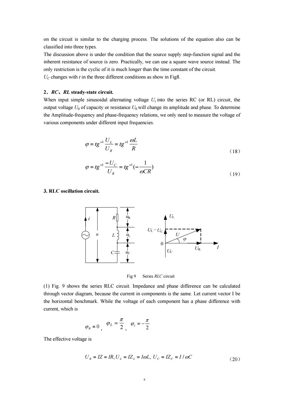
on the circuit is similar to the charging process.The solutions of the equation also can be classified into three types. The discussion above is under the condition that the source supply step-function signal and the inherent resistance of source is zero.Practically,we can use a square wave source instead.The only restriction is the cyclic of it is much longer than the time constant of the circuit. Uc changes with t in the three different conditions as show in Fig8. 2.RC.RL steady-state circuit. When input simple sinusoidal alternating voltage U;into the series RC (or RL)circuit,the output voltage Uo of capacity or resistance Uo will change its amplitude and phase.To determine the Amplitude-frequency and phase-frequency relations,we only need to measure the voltage of various components under different input frequencies. p=g业=g必 UR R (18) 9=18=18( @CR (19) 3.RLC oscillation circuit. R -Uc C 0 Fig 9 Series RLC circuit (1)Fig.9 shows the series RLC circuit.Impedance and phase difference can be calculated through vector diagram,because the current in components is the same.Let current vector I be the horizontal benchmark.While the voltage of each component has a phase difference with current,which is 2,0--2 π PR=0 PL= 2 The effective voltage is Ug IZ IR,U IZ =IoL,Uc=IZc =1/@C (20) 66 Fig 9 Series RLC circuit on the circuit is similar to the charging process. The solutions of the equation also can be classified into three types. The discussion above is under the condition that the source supply step-function signal and the inherent resistance of source is zero. Practically, we can use a square wave source instead. The only restriction is the cyclic of it is much longer than the time constant of the circuit. UC changes with t in the three different conditions as show in Fig8. 2.RC、RL steady-state circuit. When input simple sinusoidal alternating voltage Ui into the series RC (or RL) circuit, the output voltage U0 of capacity or resistance U0 will change its amplitude and phase. To determine the Amplitude-frequency and phase-frequency relations, we only need to measure the voltage of various components under different input frequencies. R L tg U U tg R L ω ϕ −1 −1 = = (18) ) 1 ( 1 1 CR tg U U tg R C ω ϕ = − − = − − (19) 3. RLC oscillation circuit. (1) Fig. 9 shows the series RLC circuit. Impedance and phase difference can be calculated through vector diagram, because the current in components is the same. Let current vector I be the horizontal benchmark. While the voltage of each component has a phase difference with current, which is ϕ R = 0 , 2 π ϕ L = , 2 π ϕc = − The effective voltage is U R = IZ = IR,U L = IZ L = IωL, UC = IZ C = I /ωC (20)