正在加载图片...

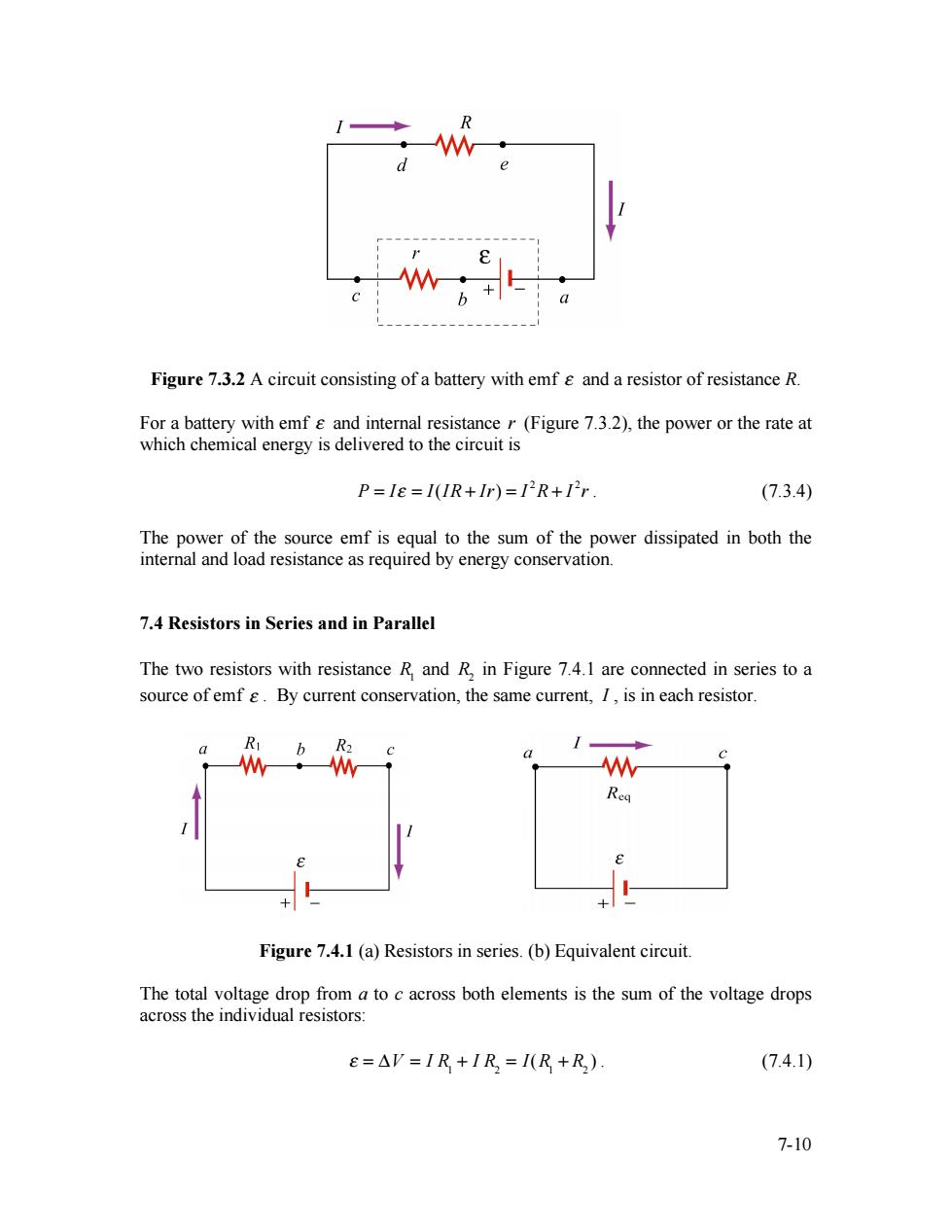
a Figure 7.3.2 A circuit consisting of a battery with emf g and a resistor of resistance R. For a battery with emf g and internal resistance r(Figure 7.3.2),the power or the rate at which chemical energy is delivered to the circuit is P=I8=1(IR+Ir)=IR+Ir. (7.3.4) The power of the source emf is equal to the sum of the power dissipated in both the internal and load resistance as required by energy conservation. 7.4 Resistors in Series and in Parallel The two resistors with resistance R and R,in Figure 7.4.1 are connected in series to a source of emf g.By current conservation,the same current,I,is in each resistor. R W Rea Figure 7.4.1 (a)Resistors in series.(b)Equivalent circuit. The total voltage drop from a to c across both elements is the sum of the voltage drops across the individual resistors: e=△V=IR+IR=I(R+R) (7.4.1) 7-107-10 Figure 7.3.2 A circuit consisting of a battery with emf ε and a resistor of resistance R. For a battery with emf ε and internal resistance r (Figure 7.3.2), the power or the rate at which chemical energy is delivered to the circuit is 2 2 P = Iε = I(IR + Ir) = I R + I r . (7.3.4) The power of the source emf is equal to the sum of the power dissipated in both the internal and load resistance as required by energy conservation. 7.4 Resistors in Series and in Parallel The two resistors with resistance R1 and R2 in Figure 7.4.1 are connected in series to a source of emf ε . By current conservation, the same current, I , is in each resistor. Figure 7.4.1 (a) Resistors in series. (b) Equivalent circuit. The total voltage drop from a to c across both elements is the sum of the voltage drops across the individual resistors: ε = ΔV = I R1 + I R2 = I(R1 + R2 ) . (7.4.1)