正在加载图片...
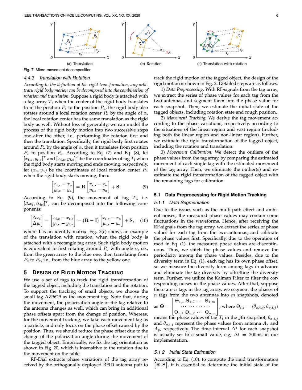
IEEE TRANSACTIONS ON MOBILE COMPUTING,VOL.XX.NO.XX,2020 oPa (a)Translation (b)Rotation (c)Translation with rotation Fig.7.Micro-movement decomposition 4.4.3 Translation with Rotation track the rigid motion of the tagged object,the design of the According to the definition of the rigid transformation,any arbi- rigid motion is shown in Fig.2.Detailed steps are as follows. trary rigid body motion can be decomposed into the combination of 1)Data Preprocessing:With RE-signals from the tag array, rotation and translation.Suppose a rigid body is attached with we extract the series of phase values for each tag from the a tag array T,when the center of the rigid body translates two antennas and segment them into the phase value for from the position P:to the position Pe,the rigid body also each snapshot.Then,we estimate the initial state of the rotates around a local rotation center Pa by the angle of a, tagged objects,including rotation state and rough position. the local rotation center has the same translation as the rigid 2)Movement Tracking:We derive the tag movement ac- body as well.Without loss of generality,we can model the cording to the phase variations,respectively,according to process of the rigid body motion into two successive steps the situations of the linear region and vast region(includ- one after the other,i.e.,performing the rotation first and ing both the linear region and non-linear region).Further, then the translation.Specifically,the rigid body first rotates we estimate the rigid transformation of the tagged object, around Pa by the angle of o,then it translates from position including the rotation and translation. P,to position Pe.According to Eq.(⑦and Eq.(⑧),let 3)Movement Calibration:We detect the outliers of the and T be the coordinates of tag T when phase values from the tag array,by comparing the estimated the rigid body starts moving and ends moving,respectively, movement of each single tag with the estimated movement let (xa,ya)be the coordinates of local rotation center Pa of the tag array.Then,we eliminate the outlier(s)and re- when the rigid body starts moving,then: estimate the rigid transformation of the tagged object with the remaining tags for calibration. -Za=RTi-Ta +S. (9) Yi.e Ya Yi,8-ya According to Eq.(9),the movement of tag Ti,i.e. 5.1 Data Preprocessing for Rigid Motion Tracking [Ari,Ayi]T,can be decomposed into the following com- 5.1.1 Data Segmentation ponents: Due to the issues such as the multi-path effect and ambi- [△ Ti.e-Ti,s ent noises,the measured phase values may contain some △ ,e-,s =(R-IE,。xa] +S,(10) yi,s-Va fluctuations in the waveforms.Hence,after receiving the RF-signals from the tag array,we extract the series of phase where I is an identity matrix.Fig.7(c)shows an example values for each tag from the two antennas,and calibrate of the translation with rotation,when the rigid body is the phase values first.Specifically,due to the operation of attached with a rectangle tag array.Such rigid body motion mod in Eq.(1),the measured phase values are discontin- is equivalent to first rotating around Pa with angle o,i.e., uous.Thus,we stitch the phase values and remove the from the green array to the blue one,then translating from periodicity among the phase values.Besides,due to the P to Pe,i.e.,from the blue array to the yellow one. diversity term in Eq.(1),each tag has its own phase offset, so we measure the diversity term among tags in advance 5 DESIGN OF RIGID MOTION TRACKING and eliminate the tag diversity by offsetting the diversity We use a set of tags to track the rigid transformation of term.Further,we utilize the Kalman Filter to filter the cor- the tagged object,including the translation and the rotation. responding noises in the phase values.After that,suppose To support the tracking of small objects,we choose the there are n tags in the tag array,we segment the phases of small tag AZ9629 as the movement tag.Note that,during n tags from the two antennas into m snapshots,denoted the movement,the polarization angle of the tag relative to Θ1,1Θ1,2…Θ1,m the antenna changes as well,which can bring in additional as⊙= whereθi,=(日z,j,fu,i,》 phase offsets apart from the change of position.Whereas, Θn.1θn,2…θn,m for the movement tracking,we take each movement tag as means the phase values of tag Ti in the jth snapshot,0r.i.j a particle,and only focus on the phase offset caused by the and 0y.i.j represent the phase values from antenna A and position.Thus,we should reduce the phase offset due to the Ay,respectively.The time interval At for each snapshot change of the polarization angle during the movement of is usually set to a small value,e.g,At 200ms in our the tagged object.Empirically,we fix the tag orientation as implementation. shown in Fig.20,which is insensitive to the rotation due to the movement on the table. 5.1.2 Initial State Estimation RF-Dial extracts phase variations of the tag array re- According to Eq.(10),to compute the rigid transformation ceived by the orthogonally deployed RFID antenna pair to R,S,it is essential to determine the initial state of theIEEE TRANSACTIONS ON MOBILE COMPUTING, VOL. XX, NO. XX, 2020 6 ௬ݏ ܲ௦ ܲ ௫ݏ ܺ ܻ ܱ (a) Translation ܺ ܻ ܲ ܲ௦ ߙ ܲ ܱ (b) Rotation ܲ ௬ݏ ௫ݏ ܲ௦(ܲ) ߙ ܺ ܻ ܱ (c) Translation with rotation Fig. 7. Micro-movement decomposition 4.4.3 Translation with Rotation According to the definition of the rigid transformation, any arbitrary rigid body motion can be decomposed into the combination of rotation and translation. Suppose a rigid body is attached with a tag array T, when the center of the rigid body translates from the position Ps to the position Pe, the rigid body also rotates around a local rotation center Pa by the angle of α, the local rotation center has the same translation as the rigid body as well. Without loss of generality, we can model the process of the rigid body motion into two successive steps one after the other, i.e., performing the rotation first and then the translation. Specifically, the rigid body first rotates around Pa by the angle of α, then it translates from position Ps to position Pe. According to Eq. (7) and Eq. (8), let [xi,s, yi,s] T and [xi,e, yi,e] T be the coordinates of tag Ti when the rigid body starts moving and ends moving, respectively, let (xa, ya) be the coordinates of local rotation center Pa when the rigid body starts moving, then: xi,e − xa yi,e − ya = R xi,s − xa yi,s − ya + S. (9) According to Eq. (9), the movement of tag Ti , i.e. [∆xi , ∆yi ] T , can be decomposed into the following components: ∆xi ∆yi = xi,e − xi,s yi,e − yi,s = (R − I) xi,s − xa yi,s − ya + S, (10) where I is an identity matrix. Fig. 7(c) shows an example of the translation with rotation, when the rigid body is attached with a rectangle tag array. Such rigid body motion is equivalent to first rotating around Pa with angle α, i.e., from the green array to the blue one, then translating from Ps to Pe, i.e., from the blue array to the yellow one. 5 DESIGN OF RIGID MOTION TRACKING We use a set of tags to track the rigid transformation of the tagged object, including the translation and the rotation. To support the tracking of small objects, we choose the small tag AZ9629 as the movement tag. Note that, during the movement, the polarization angle of the tag relative to the antenna changes as well, which can bring in additional phase offsets apart from the change of position. Whereas, for the movement tracking, we take each movement tag as a particle, and only focus on the phase offset caused by the position. Thus, we should reduce the phase offset due to the change of the polarization angle during the movement of the tagged object. Empirically, we fix the tag orientation as shown in Fig. 20, which is insensitive to the rotation due to the movement on the table. RF-Dial extracts phase variations of the tag array received by the orthogonally deployed RFID antenna pair to track the rigid motion of the tagged object, the design of the rigid motion is shown in Fig. 2. Detailed steps are as follows. 1) Data Preprocessing: With RF-signals from the tag array, we extract the series of phase values for each tag from the two antennas and segment them into the phase value for each snapshot. Then, we estimate the initial state of the tagged objects, including rotation state and rough position. 2) Movement Tracking: We derive the tag movement according to the phase variations, respectively, according to the situations of the linear region and vast region (including both the linear region and non-linear region). Further, we estimate the rigid transformation of the tagged object, including the rotation and translation. 3) Movement Calibration: We detect the outliers of the phase values from the tag array, by comparing the estimated movement of each single tag with the estimated movement of the tag array. Then, we eliminate the outlier(s) and reestimate the rigid transformation of the tagged object with the remaining tags for calibration. 5.1 Data Preprocessing for Rigid Motion Tracking 5.1.1 Data Segmentation Due to the issues such as the multi-path effect and ambient noises, the measured phase values may contain some fluctuations in the waveforms. Hence, after receiving the RF-signals from the tag array, we extract the series of phase values for each tag from the two antennas, and calibrate the phase values first. Specifically, due to the operation of mod in Eq. (1), the measured phase values are discontinuous. Thus, we stitch the phase values and remove the periodicity among the phase values. Besides, due to the diversity term in Eq. (1), each tag has its own phase offset, so we measure the diversity term among tags in advance and eliminate the tag diversity by offsetting the diversity term. Further, we utilize the Kalman Filter to filter the corresponding noises in the phase values. After that, suppose there are n tags in the tag array, we segment the phases of n tags from the two antennas into m snapshots, denoted as Θ = Θ1,1 Θ1,2 · · · Θ1,m · · · · · · · · · · · · Θn,1 Θn,2 · · · Θn,m , where Θi,j = hθx,i,j , θy,i,j i means the phase values of tag Ti in the jth snapshot, θx,i,j and θy,i,j represent the phase values from antenna Ax and Ay, respectively. The time interval ∆t for each snapshot is usually set to a small value, e.g, ∆t = 200ms in our implementation. 5.1.2 Initial State Estimation According to Eq. (10), to compute the rigid transformation R, S , it is essential to determine the initial state of the��