正在加载图片...
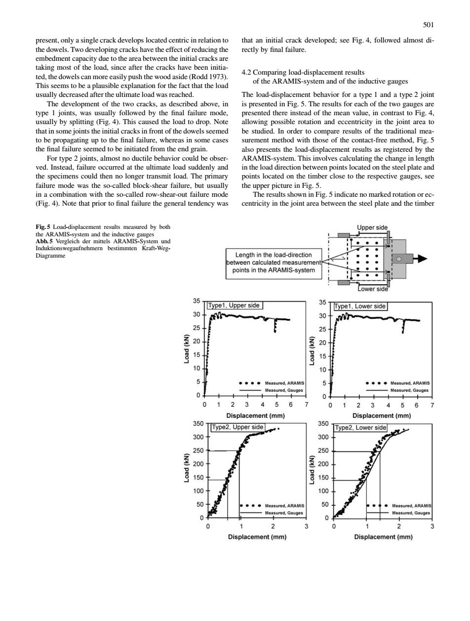
501 the do ing the embedment capacity due tothe area between the initial crack choepCbep sidelReenint ion for the fact that the load usually decreased afer them od wasreached The load-displacement behavior for a type 1 ad of t st to ally by splitting (Fig.4).This cause d the load to drop.Note wing possible rotation and eccentricity in the joint t in some je of the dowels ts the lond-displacemen t results as registered h ctile behavior could be bse MIS-system.This involves calculating the change in length he load The s located on the timber close to the on the failure mode was the so-called block-shear failure,but usually pper picture in Fig. ength in the load-direction points in the ARAMIS-system Type1,Upper side Type1,Lower side 25 20 20 10 asured,Gauges 456 t (mm) lacement (mm 350 Type2.Upper side 350 Type2,Lower side 0 300 250 200 200 150 10 100 501 present, only a single crack develops located centric in relation to the dowels. Two developing cracks have the effect of reducing the embedment capacity due to the area between the initial cracks are taking most of the load, since after the cracks have been initiated, the dowels can more easily push the wood aside (Rodd 1973). This seems to be a plausible explanation for the fact that the load usually decreased after the ultimate load was reached. The development of the two cracks, as described above, in type 1 joints, was usually followed by the final failure mode, usually by splitting (Fig. 4). This caused the load to drop. Note that in some joints the initial cracks in front of the dowels seemed to be propagating up to the final failure, whereas in some cases the final failure seemed to be initiated from the end grain. For type 2 joints, almost no ductile behavior could be observed. Instead, failure occurred at the ultimate load suddenly and the specimens could then no longer transmit load. The primary failure mode was the so-called block-shear failure, but usually in a combination with the so-called row-shear-out failure mode (Fig. 4). Note that prior to final failure the general tendency was Fig. 5 Load-displacement results measured by both the ARAMIS-system and the inductive gauges Abb. 5 Vergleich der mittels ARAMIS-System und Induktionswegaufnehmern bestimmten Kraft-WegDiagramme that an initial crack developed; see Fig. 4, followed almost directly by final failure. 4.2 Comparing load-displacement results of the ARAMIS-system and of the inductive gauges The load-displacement behavior for a type 1 and a type 2 joint is presented in Fig. 5. The results for each of the two gauges are presented there instead of the mean value, in contrast to Fig. 4, allowing possible rotation and eccentricity in the joint area to be studied. In order to compare results of the traditional measurement method with those of the contact-free method, Fig. 5 also presents the load-displacement results as registered by the ARAMIS-system. This involves calculating the change in length in the load direction between points located on the steel plate and points located on the timber close to the respective gauges, see the upper picture in Fig. 5. The results shown in Fig. 5 indicate no marked rotation or eccentricity in the joint area between the steel plate and the timber