正在加载图片...
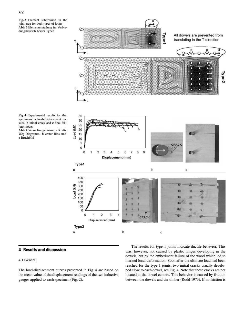
500 Fig.3 Abb.3 El ype G Fig.4 Ex ults.b i RK CRACK 0 123456789 Displacement(mm) Type 05000 2 Dis Type2 e The results for type I joints indicate ductile behavior.This 4 Results and discussion bu lure of 4.1 General eached for the type l ioints two initial cracks usually develo he nedte ped close toeach dowel,see Fig.4.Note that these cra cks are no of the disp500 Fig. 3 Element subdivision in the joint area for both types of joints Abb. 3 Elementeinteilung im Verbindungsbereich beider Typen Fig. 4 Experimental results for the specimens: a load-displacement results, b initial crack and c final failure modes Abb. 4 Versuchsergebnisse: a KraftWeg-Diagramm, b erster Riss und c Bruchbild 4 Results and discussion 4.1 General The load-displacement curves presented in Fig. 4 are based on the mean value of the displacement readings of the two inductive gauges applied to each specimen (Fig. 2). The results for type 1 joints indicate ductile behavior. This was, however, not caused by plastic hinges developing in the dowels, but by the embedment failure of the wood which led to marked local deformation. Soon after the ultimate load had been reached for the type 1 joints, two initial cracks usually developed close to each dowel, see Fig. 4. Note that these cracks are not located at the dowel centers. This behavior is caused by friction between the dowels and the timber (Rodd 1973). If no friction is