正在加载图片...
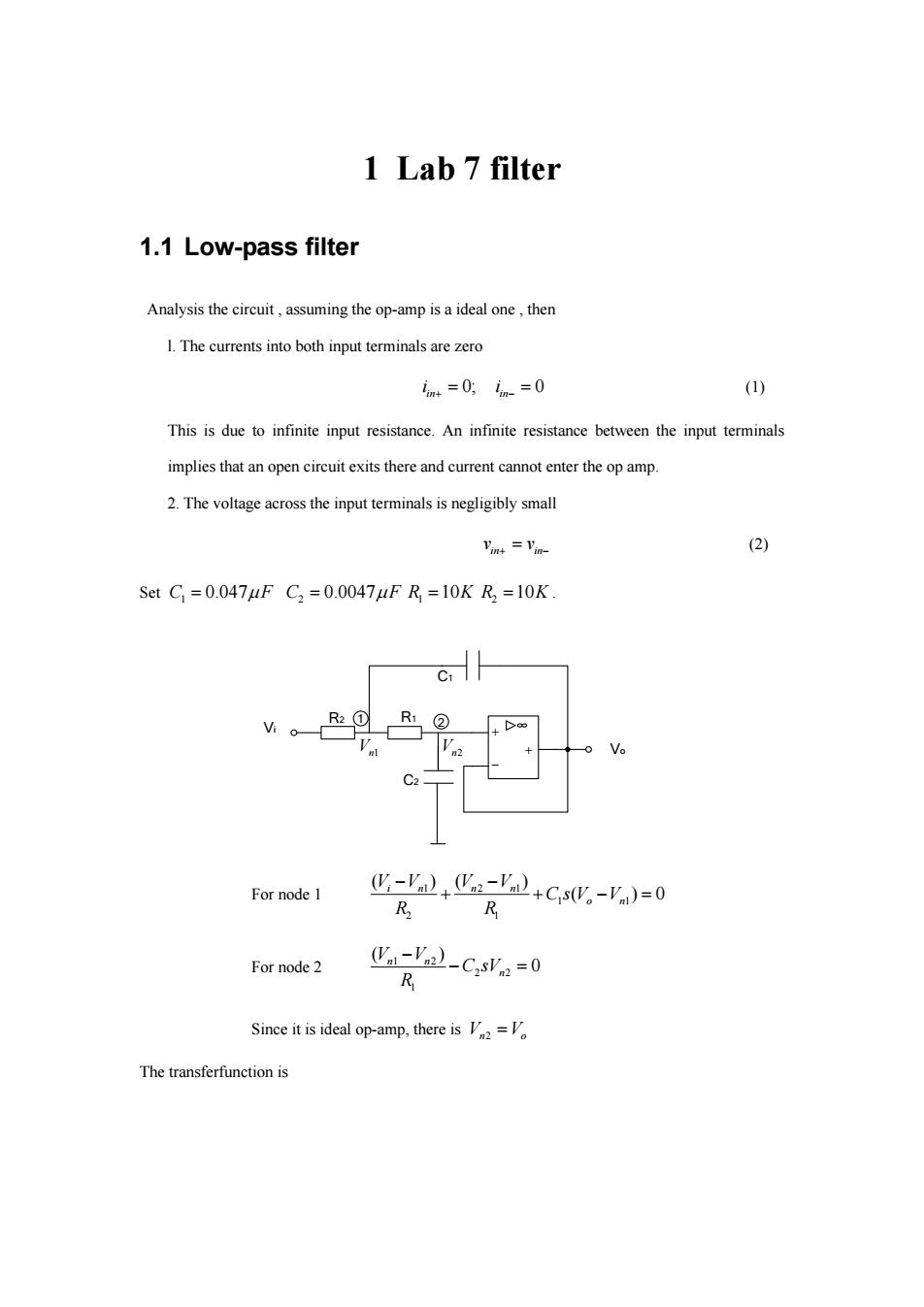
1 Lab 7 filter 1.1 Low-pass filter Analysis the circuit,assuming the op-amp is a ideal one,then 1.The currents into both input terminals are zero m+=0,n-=0 (1) This is due to infinite input resistance.An infinite resistance between the input terminals implies that an open circuit exits there and current cannot enter the op amp. 2.The voltage across the input terminals is negligibly small Vint =Vin- (2) SetC=0.047uFC2=0.0047uFR=10KR2=10K C1 For node 1 -'+a-'2+CsW。-V)=0 R R For node 2 (Va-Va)-CsVn=0 R Since it is ideal op-amp,there isV=V The transferfunction is1 Lab 7 filter 1.1 Low-pass filter Analysis the circuit , assuming the op-amp is a ideal one , then l. The currents into both input terminals are zero 0; 0 in in i i (1) This is due to infinite input resistance. An infinite resistance between the input terminals implies that an open circuit exits there and current cannot enter the op amp. 2. The voltage across the input terminals is negligibly small in in v v (2) Set 1 C F 0.047 2 C F 0.0047 1 R 10K 2 R 10K . C1 R2 R1 C2 Vo Vi 1 2 Vn1 Vn2 For node 1 1 21 1 1 2 1 ( )( ) ( )0 in n n o n VV V V CsV V R R For node 2 1 2 2 2 1 ( ) 0 n n n V V C sV R Since it is ideal op-amp, there is V V n o 2 The transferfunction is