正在加载图片...

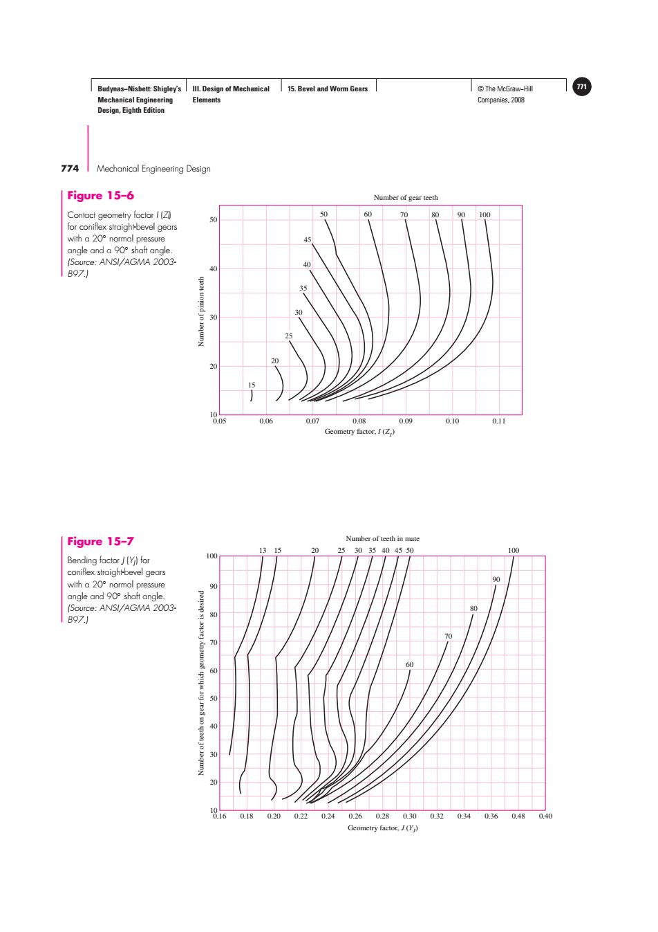
Budynas-Nisbett:Shigley's Ill.Design of Mechanical 15.Bevel and Worm Gears ©The McGraw-Hil m Mechanical Engineering Elements Companies,2008 Design,Eighth Edition 774 Mechanical Engineering Design Figure 15-6 Number of gear teeth Contact geometry factor I(Z 0 60 80 90 100 50 for coniflex straighbevel gears with a 20 normal pressure angle and a 90 shaft angle. (Source:ANSI/AGMA 2003- B97) 30 30 20 15 0.06 0.07 0.08 0.09 0.10 0.11 Gcometry factor,.I(Z) Figure 15-7 Number of teeth in mate 13 15 20 253035404550 100 Bending factor J[Y)for 100 coniflex straighi-bevel gears with a 20 normal pressure 色 angle and 90 shaft angle (Source:ANSI/AGMA 2003. B97.) 60 18160.180200220.240260280300320340360.480.40 Gcometry factor,J(Y)Budynas−Nisbett: Shigley’s Mechanical Engineering Design, Eighth Edition III. Design of Mechanical Elements 15. Bevel and Worm Gears © The McGraw−Hill 771 Companies, 2008 774 Mechanical Engineering DesignNumber of pinion teeth Geometry factor, I (ZI) 0.05 0.06 0.07 0.08 0.09 Number of gear teeth 0.10 0.11 10 20 30 40 50 15 20 25 30 35 45 50 60 70 80 90 100 40 Figure 15–6 Contact geometry factor I (ZI ) for coniflex straight-bevel gears with a 20◦ normal pressure angle and a 90◦ shaft angle. (Source: ANSI/AGMA 2003- B97.) Number of teeth on gear for which geometry factor is desired Geometry factor, J (YJ) Number of teeth in mate 0.16 0.18 0.20 0.22 0.24 0.26 0.28 0.30 0.32 0.34 0.36 0.48 0.40 10 20 30 40 50 60 13 15 20 25 30 35 40 45 50 100 90 70 80 90 100 80 70 60 Figure 15–7 Bending factor J (YJ) for coniflex straight-bevel gears with a 20◦ normal pressure angle and 90◦ shaft angle. (Source: ANSI/AGMA 2003- B97.)