正在加载图片...
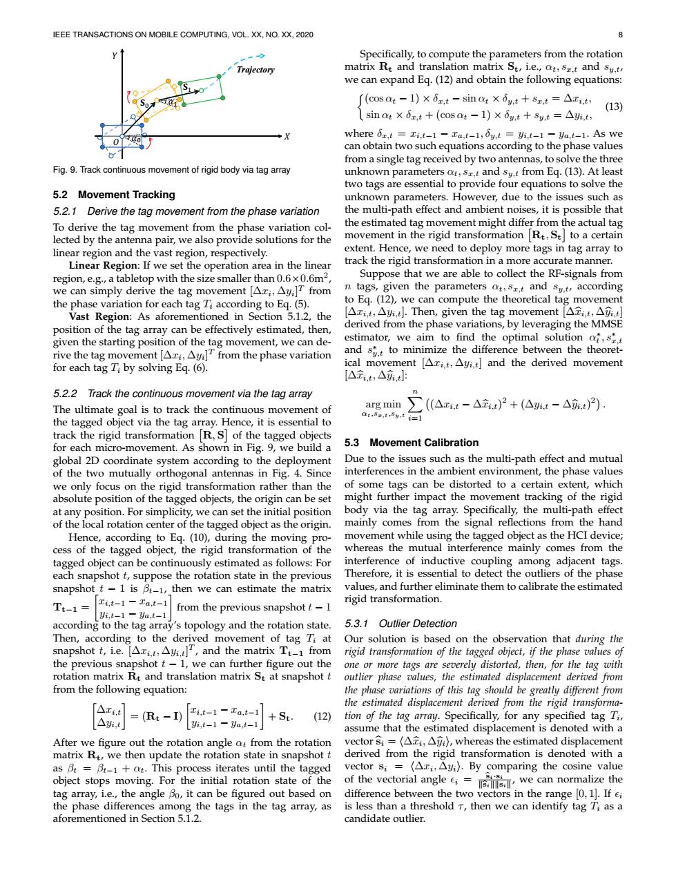
IEEE TRANSACTIONS ON MOBILE COMPUTING,VOL.XX,NO.XX,2020 8 Specifically,to compute the parameters from the rotation Trajectory matrix Rt and translation matrix St,i.e.,ot,sr.t and sy.t we can expand Eq.(12)and obtain the following equations: (COS Ot-1)×6zt-sinat×6y,t+sz,t=△xi,t, (13) .sino×0z,t+(cos at-1)×dg,t+sy,t=△,t where 6r.t Ti.t-1 -Ta,t-1,6y,t Vi.t-1-ya,t-1.As we can obtain two such equations according to the phase values from a single tag received by two antennas,to solve the three Fig.9.Track continuous movement of rigid body via tag array unknown parameters at,s,t and sy.t from Eq.(13).At least two tags are essential to provide four equations to solve the 5.2 Movement Tracking unknown parameters.However,due to the issues such as 5.2.1 Derive the tag movement from the phase variation the multi-path effect and ambient noises,it is possible that To derive the tag movement from the phase variation col- the estimated tag movement might differ from the actual tag lected by the antenna pair,we also provide solutions for the movement in the rigid transformation Rt,St to a certain linear region and the vast region,respectively. extent.Hence,we need to deploy more tags in tag array to Linear Region:If we set the operation area in the linear track the rigid transformation in a more accurate manner. region,e.g.,a tabletop with the size smaller than 0.6x0.6m2 Suppose that we are able to collect the RF-signals from we can simply derive the tag movement [Azi,Ayi]T from n tags,given the parameters ot,s.t and sy.t,according the phase variation for each tag Ti according to Eq.(5). to Eq.(12),we can compute the theoretical tag movement Vast Region:As aforementioned in Section 5.1.2,the [△xi,t,△i,t小.Then,given the tag movement[△ti,t,△i,t] position of the tag array can be effectively estimated,then, derived from the phase variations,by leveraging the MMSE given the starting position of the tag movement,we can de- estimator,we aim to find the optimal solution af,s.t rive the tag movement [Azi,AyilT from the phase variation and s.t to minimize the difference between the theoret- for each tag Ti by solving Eq.(6). ical movement [Ari.t,Ayi.t]and the derived movement [△t.t,△,t 5.2.2 Track the continuous movement via the tag array The ultimate goal is to track the continuous movement of arg min (△x.t-△金.t)2+(△班.t-△.t)2). at:8s,t,8y,t i= the tagged object via the tag array.Hence,it is essential to track the rigid transformation R,S of the tagged objects for each micro-movement.As shown in Fig.9,we build a 5.3 Movement Calibration global 2D coordinate system according to the deployment Due to the issues such as the multi-path effect and mutual of the two mutually orthogonal antennas in Fig.4.Since interferences in the ambient environment,the phase values we only focus on the rigid transformation rather than the of some tags can be distorted to a certain extent,which absolute position of the tagged objects,the origin can be set might further impact the movement tracking of the rigid at any position.For simplicity,we can set the initial position body via the tag array.Specifically,the multi-path effect of the local rotation center of the tagged object as the origin. mainly comes from the signal reflections from the hand Hence,according to Eq.(10),during the moving pro- movement while using the tagged object as the HCI device; cess of the tagged object,the rigid transformation of the whereas the mutual interference mainly comes from the tagged object can be continuously estimated as follows:For interference of inductive coupling among adjacent tags. each snapshot t,suppose the rotation state in the previous Therefore,it is essential to detect the outliers of the phase snapshot t-1 is B-1,then we can estimate the matrix values,and further eliminate them to calibrate the estimated Ti,t-1 Ta,t-1 rigid transformation. Tt-1= from the previous snapshot t-1 yi.t-1-Ya.t-1 according to the tag array's topology and the rotation state. 5.3.1 Outlier Detection Then,according to the derived movement of tag Ti at Our solution is based on the observation that during the snapshot t,i.e.[Ari.t,Ayi.t]T,and the matrix Tt-1 from rigid transformation of the tagged object,if the phase values of the previous snapshot t-1,we can further figure out the one or more tags are severely distorted,then,for the tag with rotation matrix R and translation matrix St at snapshot t outlier phase values,the estimated displacement derived from from the following equation: the phase variations of this tag should be greatly different from the estimated displacement derived from the rigid transforma- A=Re-n)-1二at +St △,t (12) tion of the tag array.Specifically,for any specified tag Ti, yi,t-1 ya,t-1 assume that the estimated displacement is denoted with a After we figure out the rotation angle ot from the rotation vector Si =(Azi,Am),whereas the estimated displacement matrix Rt,we then update the rotation state in snapshot t derived from the rigid transformation is denoted with a as B:=Bt-1+at.This process iterates until the tagged vector si=(△x,△).By comparing the cosine value object stops moving.For the initial rotation state of the of the vectorial angle c we can normalize the tag array,i.e.,the angle Bo,it can be figured out based on difference between the two vectors in the range [0,1].If ei the phase differences among the tags in the tag array,as is less than a threshold T,then we can identify tag Ti as a aforementioned in Section 5.1.2. candidate outlier.IEEE TRANSACTIONS ON MOBILE COMPUTING, VOL. XX, NO. XX, 2020 8 ܺ ܻ ߙ ଵߙ ܁ ଵ܁ Trajectory ܱ Fig. 9. Track continuous movement of rigid body via tag array 5.2 Movement Tracking 5.2.1 Derive the tag movement from the phase variation To derive the tag movement from the phase variation collected by the antenna pair, we also provide solutions for the linear region and the vast region, respectively. Linear Region: If we set the operation area in the linear region, e.g., a tabletop with the size smaller than 0.6×0.6m2 , we can simply derive the tag movement [∆xi , ∆yi ] T from the phase variation for each tag Ti according to Eq. (5). Vast Region: As aforementioned in Section 5.1.2, the position of the tag array can be effectively estimated, then, given the starting position of the tag movement, we can derive the tag movement [∆xi , ∆yi ] T from the phase variation for each tag Ti by solving Eq. (6). 5.2.2 Track the continuous movement via the tag array The ultimate goal is to track the continuous movement of the tagged object via the tag array. Hence, it is essential to track the rigid transformation R, S of the tagged objects for each micro-movement. As shown in Fig. 9, we build a global 2D coordinate system according to the deployment of the two mutually orthogonal antennas in Fig. 4. Since we only focus on the rigid transformation rather than the absolute position of the tagged objects, the origin can be set at any position. For simplicity, we can set the initial position of the local rotation center of the tagged object as the origin. Hence, according to Eq. (10), during the moving process of the tagged object, the rigid transformation of the tagged object can be continuously estimated as follows: For each snapshot t, suppose the rotation state in the previous snapshot t − 1 is βt−1, then we can estimate the matrix Tt−1 = xi,t−1 − xa,t−1 yi,t−1 − ya,t−1 from the previous snapshot t − 1 according to the tag array’s topology and the rotation state. Then, according to the derived movement of tag Ti at snapshot t, i.e. [∆xi,t, ∆yi,t] T , and the matrix Tt−1 from the previous snapshot t − 1, we can further figure out the rotation matrix Rt and translation matrix St at snapshot t from the following equation: ∆xi,t ∆yi,t = (Rt − I) xi,t−1 − xa,t−1 yi,t−1 − ya,t−1 + St. (12) After we figure out the rotation angle αt from the rotation matrix Rt, we then update the rotation state in snapshot t as βt = βt−1 + αt. This process iterates until the tagged object stops moving. For the initial rotation state of the tag array, i.e., the angle β0, it can be figured out based on the phase differences among the tags in the tag array, as aforementioned in Section 5.1.2. Specifically, to compute the parameters from the rotation matrix Rt and translation matrix St, i.e., αt, sx,t and sy,t, we can expand Eq. (12) and obtain the following equations: (cos αt − 1) × δx,t − sin αt × δy,t + sx,t = ∆xi,t, sin αt × δx,t + (cos αt − 1) × δy,t + sy,t = ∆yi,t, (13) where δx,t = xi,t−1 − xa,t−1, δy,t = yi,t−1 − ya,t−1. As we can obtain two such equations according to the phase values from a single tag received by two antennas, to solve the three unknown parameters αt, sx,t and sy,t from Eq. (13). At least two tags are essential to provide four equations to solve the unknown parameters. However, due to the issues such as the multi-path effect and ambient noises, it is possible that the estimated tag movement might differ from the actual tag movement in the rigid transformation Rt, St to a certain extent. Hence, we need to deploy more tags in tag array to track the rigid transformation in a more accurate manner. Suppose that we are able to collect the RF-signals from n tags, given the parameters αt, sx,t and sy,t, according to Eq. (12), we can compute the theoretical tag movement [∆xi,t, ∆yi,t]. Then, given the tag movement [∆xbi,t, ∆ybi,t] derived from the phase variations, by leveraging the MMSE estimator, we aim to find the optimal solution α ∗ t , s∗ x,t and s ∗ y,t to minimize the difference between the theoretical movement [∆xi,t, ∆yi,t] and the derived movement [∆xbi,t, ∆ybi,t]: arg min αt,sx,t,sy,t Xn i=1 (∆xi,t − ∆xbi,t) 2 + (∆yi,t − ∆ybi,t) 2 . 5.3 Movement Calibration Due to the issues such as the multi-path effect and mutual interferences in the ambient environment, the phase values of some tags can be distorted to a certain extent, which might further impact the movement tracking of the rigid body via the tag array. Specifically, the multi-path effect mainly comes from the signal reflections from the hand movement while using the tagged object as the HCI device; whereas the mutual interference mainly comes from the interference of inductive coupling among adjacent tags. Therefore, it is essential to detect the outliers of the phase values, and further eliminate them to calibrate the estimated rigid transformation. 5.3.1 Outlier Detection Our solution is based on the observation that during the rigid transformation of the tagged object, if the phase values of one or more tags are severely distorted, then, for the tag with outlier phase values, the estimated displacement derived from the phase variations of this tag should be greatly different from the estimated displacement derived from the rigid transformation of the tag array. Specifically, for any specified tag Ti , assume that the estimated displacement is denoted with a vector bsi = h∆xbi , ∆ybii, whereas the estimated displacement derived from the rigid transformation is denoted with a vector si = h∆xi , ∆yii. By comparing the cosine value of the vectorial angle i = bsi·si kbsikksik , we can normalize the difference between the two vectors in the range [0, 1]. If i is less than a threshold τ , then we can identify tag Ti as a candidate outlier.����