正在加载图片...
Gong Zhichao et al. October 2009 A3 AA ●P Fig.8.Small-signal noise equivalent circuit for noise analysis because M9-M16 are cascode transistors.The small-signal -225 。calculated circuit for noise analysis is shown in Fig. :.... 一simulated 235 are the equivalent resistance,transconductance and noise of (ZH/Vap) the replica circuit,respectively.Gand A3 are the gain and in- 245 ,二g00oo的9ne0e0mo4 replica put equivalent noise of amplifier A3.are the noise M17-M20 of resister R and transistor M17 255 The continuous output current noise can be obtained from Fig.8 and simplified as 265 2100 10k 100k 10M nc,out Frequency (Hz) Fig.9.Calculated and simulated output current noise of the differen tial CP circuit. 1/sC1 8m.M9 R1+1/sC1 .M17 8m.M9 gds.M9 gds.M17 the noise contribution to the continuous output current noise (3) from the thermal noise of transistor M17. After the PLL is locked.is sampled out every T sec- Figure 9 shows the calculated and simulated output cur- onds.Each sample lasts for a period ofr.The spectrum of the rent noise of the differential CP circuit and noise contribu- sampling function is tion from different circuit components.The calculation re- s=) sin(πtnlT) sult agrees well with the simulation.In frequencies below n=0,±1,±2,..· (4) n 1 kHz the dominant noise contribution comes from both the So. replica and transistors M17-M20.In frequencies above 1 kHz the dominant noise contribution only comes from transistors = sin(πt/T) (5) M17-M20.The noise contribution from the replica decreases Sampled output current noise can be calculated through con- rapidly between 100 Hz and 100 kHz because the bandwidth volution betweenand f).In the convolution,the num- of the replica loop with a dominant pole at node RP (or RN) is less than 1 kHz.The non-dominant pole about at 2 MHz ber of sampling function harmonics which should be consid- comes from Ri and Ci (or R2 and C2). ered is related to the bandwidth of the noise.The bandwidth of The current noise from the CMFB circuit is not sampled. the noise contribution from the replica,resister RI and flicker Only transistors M6-M9 in Fig.6 contribute noise.The noise noise of transistor M17 is much smaller than 1/T,so only the from other parts is common-mode noise.Thus,the output cur- DC component of the sampling function needs to be consid- rent noise of the CMFB circuit is ered.The bandwidth of the noise contribution from the thermal noise of transistor M17 is almost unlimited,so all sampling (8) function harmonics need to be considered.Thus,the sampled output current noise can be obtained as whereandare current noise of transistors M6 and a=S02(p++Mn+e2孟Mm (6) M7 respectively. Figure 10 shows the simulated output current noise of where the differential CP circuit with and without common-source -2-别 (7) capacitors.It can be seen that the noise contribution from the CMFB circuit can be neglected.The simulation reveals that large common-source capacitors deteriorate noise perfor- put current noise from the replica and resister Ri respectively. mance greatly,especially at low frequencies.The reason for this is that switching transistors M9-M16 become the main isthe noise contribution to the continuous ouput cur noise contribution due to the complicated time-varying char- rent noise from the flicker noise of transistor M17.is acteristics of the differential CP circuit. 105013-4Gong Zhichao et al. October 2009 Fig. 8. Small-signal noise equivalent circuit for noise analysis. because M9–M16 are cascode transistors. The small-signal circuit for noise analysis is shown in Fig. 8. Rrpl, gmrpl, v 2 n,rpl are the equivalent resistance, transconductance and noise of the replica circuit, respectively. G and v 2 n, A3 are the gain and input equivalent noise of amplifier A3. v 2 n,r1, i 2 n, M17 are the noise of resister R1 and transistor M17. The continuous output current noise can be obtained from Fig. 8 and simplified as i 2 nc, out ≈ v 2 n, rpl + v 2 n, A3
gmrpl [ Rrpl||( 1 / sCrpl)]
2 + v 2 n, r1 ×
1/sC1 R1 + 1/sC1
2 g 2 m,m17 + i 2 n, M17
gm, M9 gm, M9 + gds, M9 + gds, M17
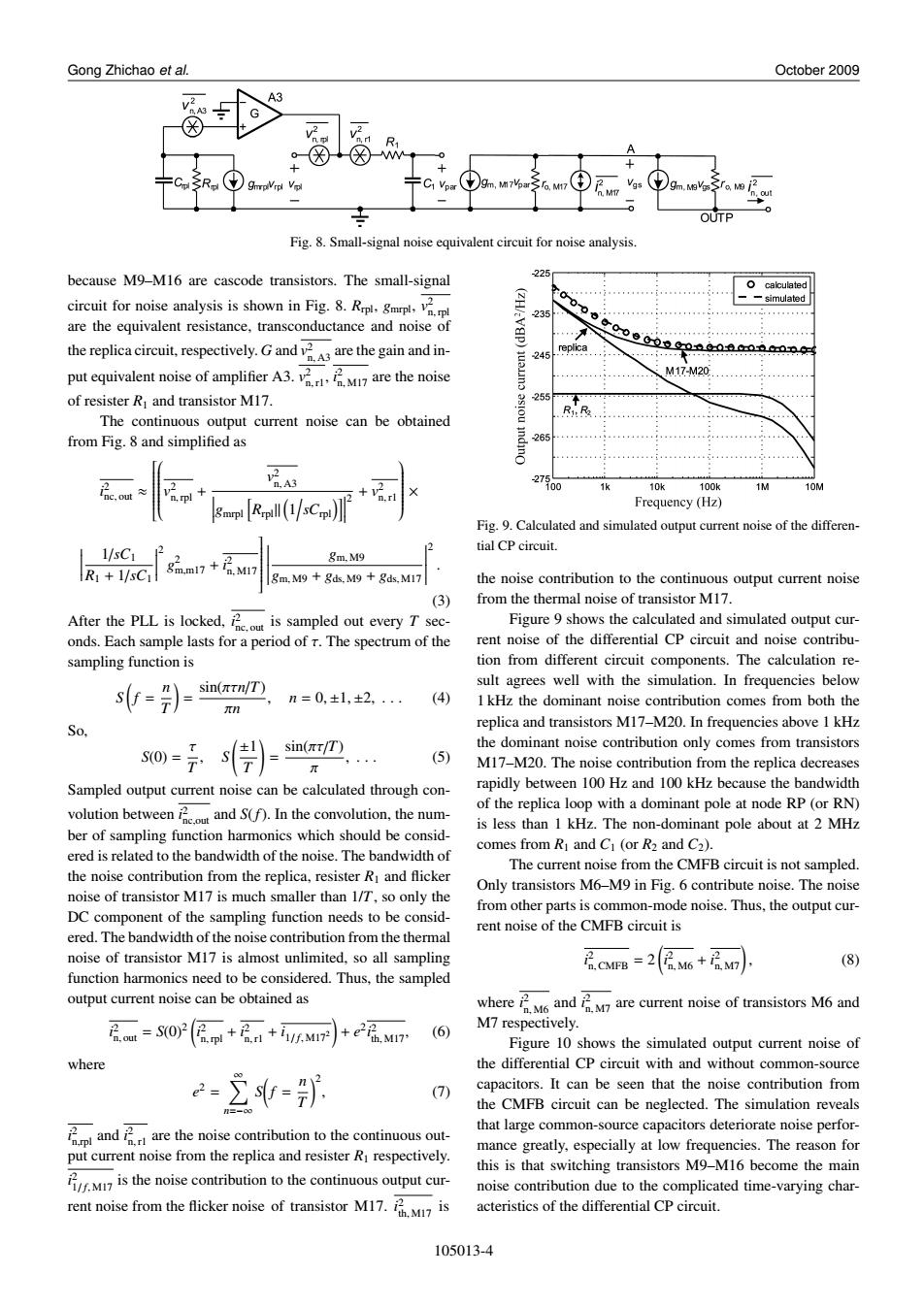
2 . (3) After the PLL is locked, i 2 nc, out is sampled out every T seconds. Each sample lasts for a period of τ. The spectrum of the sampling function is S ( f = n T ) = sin(πτn/T) πn , n = 0, ±1, ±2, . . . (4) So, S(0) = τ T , S ( ±1 T ) = sin(πτ/T) π , . . . (5) Sampled output current noise can be calculated through convolution between i 2 nc,out and S(f). In the convolution, the number of sampling function harmonics which should be considered is related to the bandwidth of the noise. The bandwidth of the noise contribution from the replica, resister R1 and flicker noise of transistor M17 is much smaller than 1/T, so only the DC component of the sampling function needs to be considered. The bandwidth of the noise contribution from the thermal noise of transistor M17 is almost unlimited, so all sampling function harmonics need to be considered. Thus, the sampled output current noise can be obtained as i 2 n, out = S(0)2 ( i 2 n, rpl + i 2 n, r1 + i1/ f, M172 ) + e 2 i 2 th, M17, (6) where e 2 = ∑∞ n=−∞ S ( f = n T )2 , (7) i 2 n,rpl and i 2 n,r1 are the noise contribution to the continuous output current noise from the replica and resister R1 respectively. i 2 1/ f, M17 is the noise contribution to the continuous output current noise from the flicker noise of transistor M17. i 2 th, M17 is Fig. 9. Calculated and simulated output current noise of the differential CP circuit. the noise contribution to the continuous output current noise from the thermal noise of transistor M17. Figure 9 shows the calculated and simulated output current noise of the differential CP circuit and noise contribution from different circuit components. The calculation result agrees well with the simulation. In frequencies below 1 kHz the dominant noise contribution comes from both the replica and transistors M17–M20. In frequencies above 1 kHz the dominant noise contribution only comes from transistors M17–M20. The noise contribution from the replica decreases rapidly between 100 Hz and 100 kHz because the bandwidth of the replica loop with a dominant pole at node RP (or RN) is less than 1 kHz. The non-dominant pole about at 2 MHz comes from R1 and C1 (or R2 and C2). The current noise from the CMFB circuit is not sampled. Only transistors M6–M9 in Fig. 6 contribute noise. The noise from other parts is common-mode noise. Thus, the output current noise of the CMFB circuit is i 2 n, CMFB = 2 ( i 2 n, M6 + i 2 n, M7) , (8) where i 2 n, M6 and i 2 n, M7 are current noise of transistors M6 and M7 respectively. Figure 10 shows the simulated output current noise of the differential CP circuit with and without common-source capacitors. It can be seen that the noise contribution from the CMFB circuit can be neglected. The simulation reveals that large common-source capacitors deteriorate noise performance greatly, especially at low frequencies. The reason for this is that switching transistors M9–M16 become the main noise contribution due to the complicated time-varying characteristics of the differential CP circuit. 105013-4