正在加载图片...
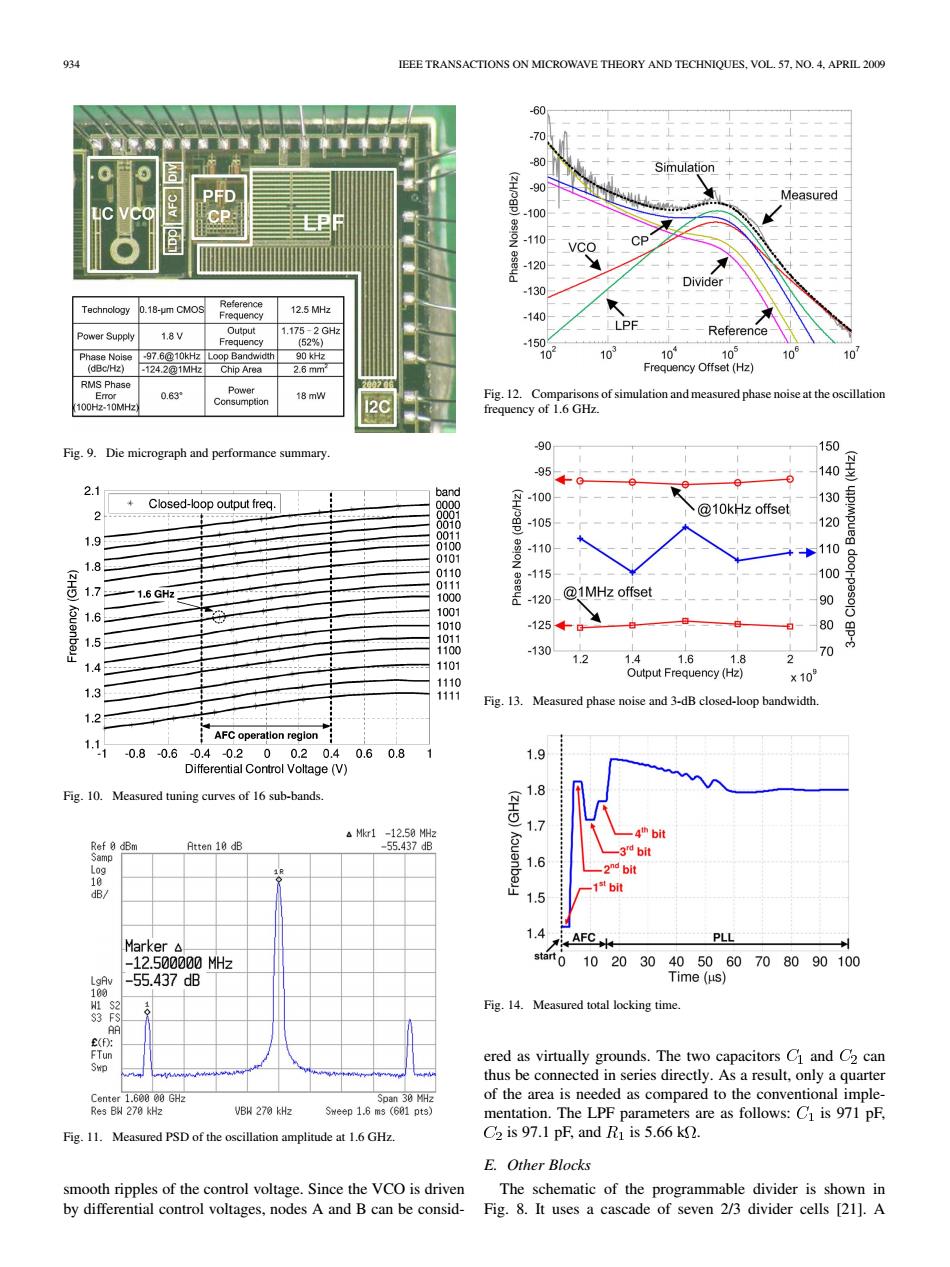
IEEE TRANSACTIONS ON MICROWAVE THEORY AND TECHNIQUES.VOL.57.NO.4.APRIL 2009 -60 70 80 Simulation -90 Measured -100 -110 VCO CP -120 Divider -130 Technology 0.18-um CMOS Reference 12.5 MHz Frequency -140 Power Supply 1.8V Output 1.175-2GHz Reference Frequency (52%) .150 Phase Nolse -97.6@10kHz Loop Bandwidth 90 kHz 103 o 10¥ 105 106 101 (dBc/Hz) -124.201MHz Chip Area 2.6mm Frequency Offset(Hz) RMS Phase Eror 0.63 Power Fig.12.Comparisons of simulation and measured phase noise at the oscillation 100H2-10MHz Consumption 18 mW 20 frequency of 1.6 GHz. Fig.9.Die micrograph and performance summary. -90 150 -95 140 2.1 band +Closed-loop output freq. -100 130 2 89 @10kHz offset -105 120 1.9 -110 110 1.8 -115 100 1.7 8i9 -1.6GHz二 1000 120 @1MHz offset 90 1.6 1001 1010 .125★0 80 1.5 1011 1100 -130 1101 1.2 1.41.61.8 d 14 Output Frequency (Hz) 1110 ×10 1.3 1111 Fig.13. Measured phase noise and 3-dB closed-loop bandwidth. 1.21 AFC operation region 0.8-0.6-0.4-020 0.20.4 0.60.8 1 1.9 Differential Control Voltage (V) Fig.10.Measured tuning curves of 16 sub-bands. 1.8 a Mkr1 -12.50 MHz Ref 8 dBm Atten 10 dB -55.437dB Samp -3 bit 1.6 2nd bit 10 dB/ ,1数b 1.5 1.4 AFC PLL Marker△ -12.500000MHz stat0102030 405060708090100 LgAv -55.437dB Time(μs) 100 Fig.14.Measured total locking time FS AA ered as virtually grounds.The two capacitors C and C2 can Swp thus be connected in series directly.As a result,only a quarter Center 1.600 00 GHz Span 30 MHz of the area is needed as compared to the conventional imple- Res BW 270 kHz VBH 270 kHz meep1.6m3(691pts】 mentation.The LPF parameters are as follows:Cl is 971 pF, Fig.11.Measured PSD of the oscillation amplitude at 1.6 GHz. C2 is 97.1 pF,and Ri is 5.66 k2. E.Other Blocks smooth ripples of the control voltage.Since the VCO is driven The schematic of the programmable divider is shown in by differential control voltages,nodes A and B can be consid- Fig.8.It uses a cascade of seven 2/3 divider cells [21].A934 IEEE TRANSACTIONS ON MICROWAVE THEORY AND TECHNIQUES, VOL. 57, NO. 4, APRIL 2009 Fig. 9. Die micrograph and performance summary. Fig. 10. Measured tuning curves of 16 sub-bands. Fig. 11. Measured PSD of the oscillation amplitude at 1.6 GHz. smooth ripples of the control voltage. Since the VCO is driven by differential control voltages, nodes A and B can be considFig. 12. Comparisons of simulation and measured phase noise at the oscillation frequency of 1.6 GHz. Fig. 13. Measured phase noise and 3-dB closed-loop bandwidth. Fig. 14. Measured total locking time. ered as virtually grounds. The two capacitors and can thus be connected in series directly. As a result, only a quarter of the area is needed as compared to the conventional implementation. The LPF parameters are as follows: is 971 pF, is 97.1 pF, and is 5.66 k . E. Other Blocks The schematic of the programmable divider is shown in Fig. 8. It uses a cascade of seven 2/3 divider cells [21]. A