正在加载图片...
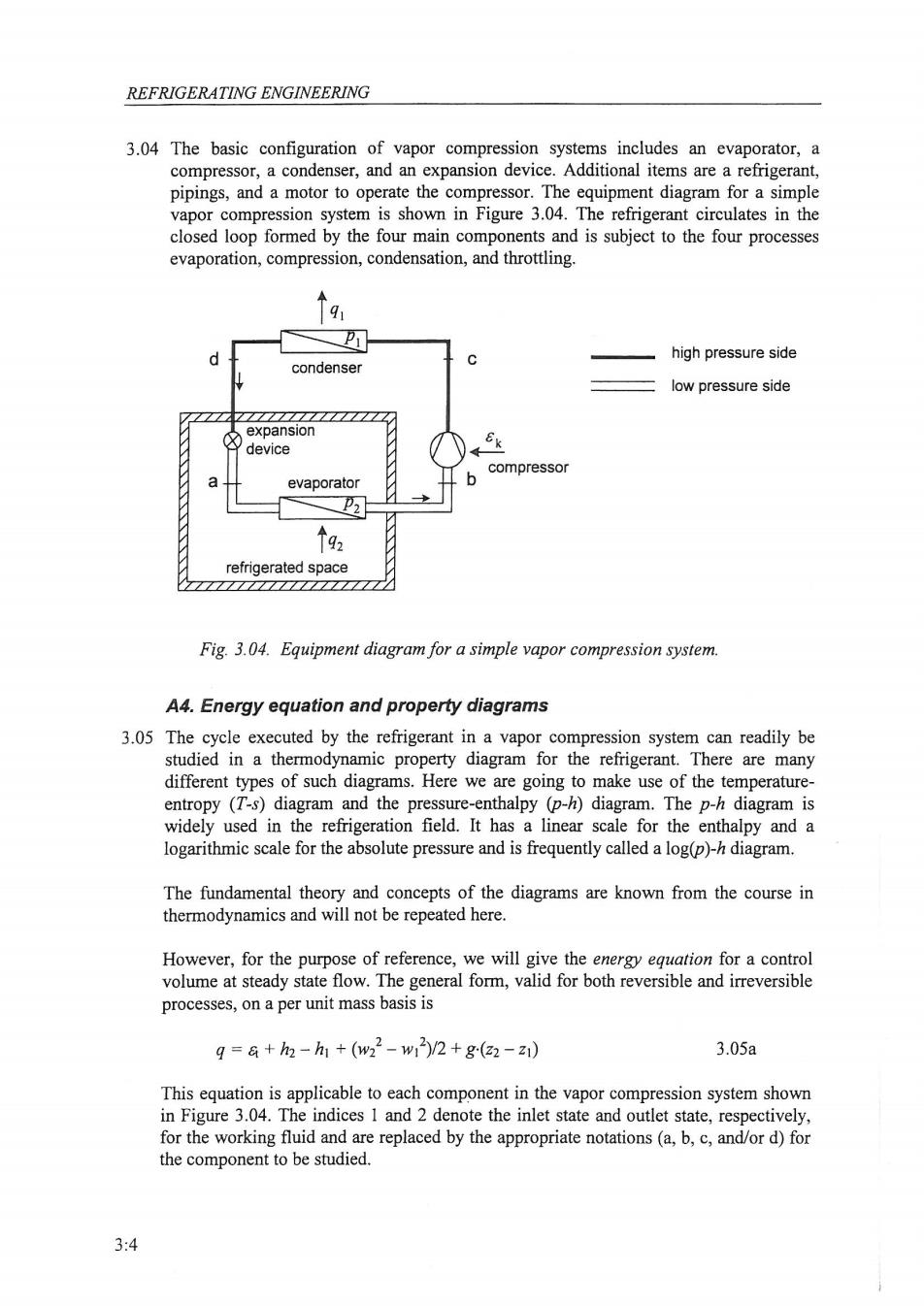
REFRIGERATING ENGINEERING 3.04 The basic configuration of vapor compression systems includes an evaporator,a compressor,a condenser,and an expansion device.Additional items are a refrigerant, pipings,and a motor to operate the compressor.The equipment diagram for a simple vapor compression system is shown in Figure 3.04.The refrigerant circulates in the closed loop formed by the four main components and is subject to the four processes evaporation,compression,condensation,and throttling. high pressure side condenser low pressure side expansion device compressor a evaporator 个92 refrigerated space Fig.3.04.Equipment diagram for a simple vapor compression system. A4.Energy equation and property diagrams 3.05 The cycle executed by the refrigerant in a vapor compression system can readily be studied in a thermodynamic property diagram for the refrigerant.There are many different types of such diagrams.Here we are going to make use of the temperature- entropy (T-s)diagram and the pressure-enthalpy (p-h)diagram.The p-h diagram is widely used in the refrigeration field.It has a linear scale for the enthalpy and a logarithmic scale for the absolute pressure and is frequently called a log(p)-h diagram. The fundamental theory and concepts of the diagrams are known from the course in thermodynamics and will not be repeated here. However,for the purpose of reference,we will give the energy equation for a control volume at steady state flow.The general form,valid for both reversible and irreversible processes,on a per unit mass basis is g=a+h2-h1+(w22-w1)/2+g(22-z1) 3.05a This equation is applicable to each component in the vapor compression system shown in Figure 3.04.The indices 1 and 2 denote the inlet state and outlet state,respectively, for the working fluid and are replaced by the appropriate notations(a,b,c,and/or d)for the component to be studied. 3:4