正在加载图片...
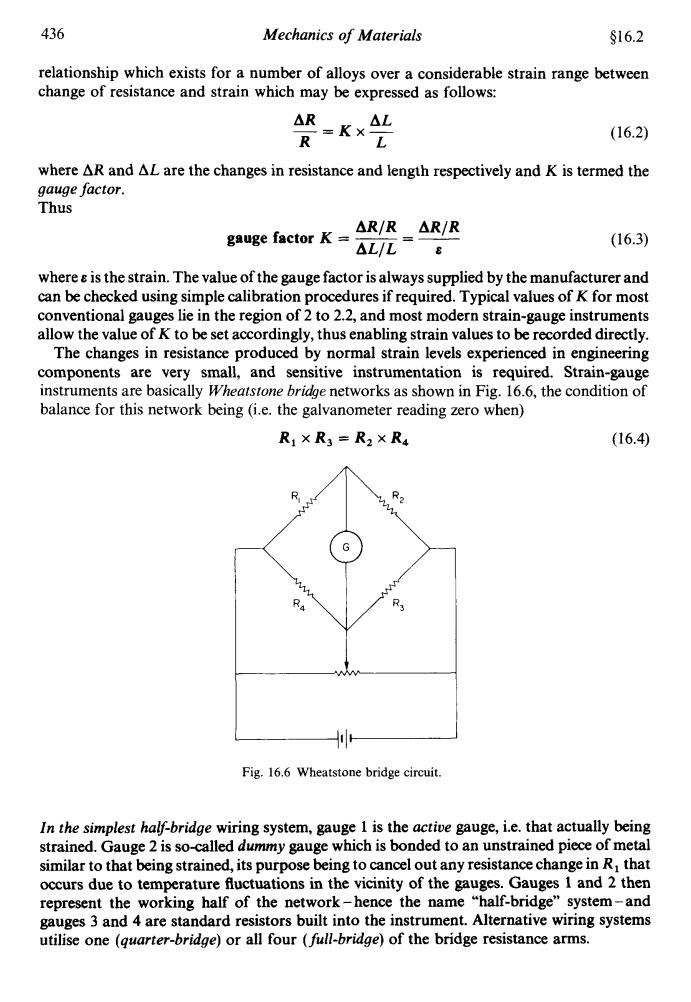
436 Mechanics of Materials $16.2 relationship which exists for a number of alloys over a considerable strain range between change of resistance and strain which may be expressed as follows: △Rx△L =Kx- R (16.2) L where AR and AL are the changes in resistance and length respectively and K is termed the gauge factor. Thus △R/R△R/R gauge factor K △L/L8 (16.3) where is the strain.The value of the gauge factor is always supplied by the manufacturer and can be checked using simple calibration procedures if required.Typical values of K for most conventional gauges lie in the region of 2 to 2.2,and most modern strain-gauge instruments allow the value of K to be set accordingly,thus enabling strain values to be recorded directly. The changes in resistance produced by normal strain levels experienced in engineering components are very small,and sensitive instrumentation is required.Strain-gauge instruments are basically Wheatstone bridge networks as shown in Fig.16.6,the condition of balance for this network being (i.e.the galvanometer reading zero when) R1×R3=R2XR4 (16.4) R 2 R3 Fig.16.6 Wheatstone bridge circuit. In the simplest half-bridge wiring system,gauge 1 is the active gauge,i.e.that actually being strained.Gauge 2 is so-called dummy gauge which is bonded to an unstrained piece of metal similar to that being strained,its purpose being to cancel out any resistance change in R that occurs due to temperature fluctuations in the vicinity of the gauges.Gauges 1 and 2 then represent the working half of the network-hence the name "half-bridge"system-and gauges 3 and 4 are standard resistors built into the instrument.Alternative wiring systems utilise one (guarter-bridge)or all four (full-bridge)of the bridge resistance arms.436 Mechanics of Materials $16.2 relationship which exists for a number of alloys over a considerable strain range between change of resistance and strain which may be expressed as follows: AR AL R L -=Kx- (16.2) where AR and AL are the changes in resistance and length respectively and K is termed the gauge factor. Thus ARfR ARfR gauge factor K = - ALfL - - 7 (16.3) where e is the strain. The value of the gauge factor is always supplied by the manufacturer and can be checked using simple calibration procedures if required. Typical values of K for most conventional gauges lie in the region of 2 to 2.2, and most modern strain-gauge instruments allow the value of K to be set accordingly, thus enabling strain values to be recorded directly. The changes in resistance produced by normal strain levels experienced in engineering components are very small, and sensitive instrumentation is required. Strain-gauge instruments are basically Wheatstone brihe networks as shown in Fig. 16.6, the condition of balance for this network being (i.e. the galvanometer reading zero when) R, x R3 = R, x R4 (16.4) -11- Fig. 16.6 Wheatstone bridge circuit. In the simplest half-bridge wiring system, gauge 1 is the actioe gauge, i.e. that actually being strained. Gauge 2 is so-called dummy gauge which is bonded to an unstrained piece of metal similar to that being strained, its purpose being to cancel out any resistance change in R, that occurs due to temperature fluctuations in the vicinity of the gauges. Gauges 1 and 2 then represent the working half of the network - hence the name “half-bridge” system - and gauges 3 and 4 are standard resistors built into the instrument. Alternative wiring systems utilise one (quarter-bridge) or all four (full-bridge) of the bridge resistance arms