正在加载图片...
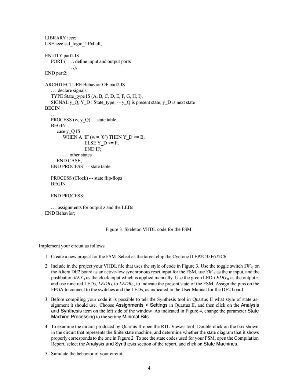
ENTITY part2 IS PORT(...define input and output ports END part2: ARCHITECTURE Behavior OF part2 IS IS (A.B.C.D.E.F.G,H.D): SIGNALy Q.Y_D:State_type: --yQis present state,yD is next state BEGIN casey_QIS WHEN A IF (w='0')THEN Y_D<=B, YD<=F; other states END CASE: END PROCESS;--state table PROCESS(Clock)--state flip-flops BEGIN END PROCESS: assignments for outputz and the LEDs END Behavior. Figure 3.Skeleton VHDL code for the FSM Implement your circuit as follows. 1.Create a new project for the FSM.Select as the target chip the Cyelone lI EP2C35F672C6 2.Include in the project your VHDL file that uses the style of code in Figure3.Use the toggle switchW the Altera DE bod as an activ-ow ,and the the anually. e the green L o as th e outpu he switchesand the LEDs.s indicated n the User Manual for the DE2 board. 3.Before compilir your code it is possible to tell the Synthesis tool in Ouartus Il what stvle of state as shouldChoosegmentsngQuand then cik thnyss nd Synthesis item on the left side I the wi w.As indicated in Figure 4.change the parameter State Processing to the setting Minimal Bits y Ouartus I oroperly corresponds to the one in Figure 2.To see the state codes used for your FSM,o en the Compilation Report,select the Analysis and Synthesis section of the report,and click on State Machines. 5.Simulate the behavior of your cireuitLIBRARY ieee; USE ieee.std_logic_1164.all; ENTITY part2 IS PORT ( ... define input and output ports ...); END part2; ARCHITECTURE Behavior OF part2 IS ... declare signals TYPE State_type IS (A, B, C, D, E, F, G, H, I); SIGNAL y_Q, Y_D : State_type; - - y_Q is present state, y_D is next state BEGIN ... PROCESS (w, y_Q) - - state table BEGIN case y_Q IS WHEN A IF (w = ’0’) THEN Y_D <= B; ELSE Y_D <= F; END IF; ... other states END CASE; END PROCESS; - - state table PROCESS (Clock) - - state flip-flops BEGIN ... END PROCESS; ... assignments for output z and the LEDs END Behavior; Figure 3. Skeleton VHDL code for the FSM. Implement your circuit as follows. 1. Create a new project for the FSM. Select as the target chip the Cyclone II EP2C35F672C6. 2. Include in the project your VHDL file that uses the style of code in Figure 3. Use the toggle switch SW 0 on the Altera DE2 board as an active-low synchronous reset input for the FSM, use SW 1 as the w input, and the pushbutton KEY0 as the clock input which is applied manually. Use the green LED LEDG0 as the output z, and use nine red LEDs, LEDR8 to LEDR0, to indicate the present state of the FSM. Assign the pins on the FPGA to connect to the switches and the LEDs, as indicated in the User Manual for the DE2 board. 3. Before compiling your code it is possible to tell the Synthesis tool in Quartus II what style of state assignment it should use. Choose Assignments > Settings in Quartus II, and then click on the Analysis and Synthesis item on the left side of the window. As indicated in Figure 4, change the parameter State Machine Processing to the setting Minimal Bits. 4. To examine the circuit produced by Quartus II open the RTL Viewer tool. Double-click on the box shown in the circuit that represents the finite state machine, and determine whether the state diagram that it shows properly corresponds to the one in Figure 2. To see the state codes used for your FSM, open the Compilation Report, select the Analysis and Synthesis section of the report, and click on State Machines. 5. Simulate the behavior of your circuit. 4