正在加载图片...

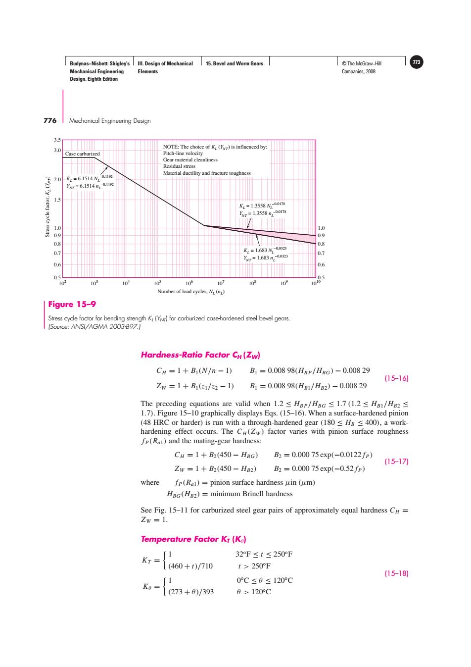
Budynas-Nisbett:Shigley's Ill.Design of Mechanical 15.Bevel and Worm Gears ©The McGraw-Hil 3 Mechanical Engineering Elements Companies,2008 Design,Eighth Edition 776 IMechanical Engineering Design 35 3.0 NOTE:The choice of K (Yr)is influenced by: Case carburized Pitch-line velocity Gear material cleanliness Residual stress Material ductility and fracture toughness K=6.1514N,-a12 Vr=6.1514n2a12 1.5 KL=1.3558N2-00178 r=1.3558-0017 1.0 1.0 0.9 0.9 0.8 K=1.683N-0s3 0.8 0.7 Xr=1.683m,0.au 0.7 0.6 0.6 0 103 103 10 10 10 10 103 10' Number of load cycles.N (np) Figure 15-9 Stress cycle factor for bending strength K(YN)for carburized case-hardened steel bevel gears. (Source:ANSI/AGMA 2003-B97.] Hardness-Ratio Factor CH(Zw) CH=1+B1(N/n-1)B1=0.00898(HBP/HBG)-0.00829 (15-16) Zw=1+B1(31/22-1) B1=0.00898(HB1/HB2)-0.00829 The preceding equations are valid when1.2≤Hgr/HaG≤l.7(l.2≤Hg1/Ha2≤ 1.7).Figure 15-10 graphically displays Eqs.(15-16).When a surface-hardened pinion (48 HRC or harder)is run with a through-hardened gear(180 Hg <400),a work- hardening effect occurs.The Cu(Zw)factor varies with pinion surface roughness fp(Ra)and the mating-gear hardness: CH=1+B2(450-HBG) B2=0.00075exp(-0.0122fp) (15-17刀 Zw=1+B2(450-HB2) B2=0.00075exp(-0.52fp) where fp(R)=pinion surface hardness uin (um) HBG(H82)=minimum Brinell hardness See Fig.15-11 for carburized steel gear pairs of approximately equal hardness CH= Zw=1. Temperature Factor KT(Ke) 1 32F≤t≤250°F KT= (460+t)/710 t>250°℉ (15-18) 0°C≤0≤120°C Ka= (273+0)/393 0>120CBudynas−Nisbett: Shigley’s Mechanical Engineering Design, Eighth Edition III. Design of Mechanical Elements 15. Bevel and Worm Gears © The McGraw−Hill 773 Companies, 2008 776 Mechanical Engineering Design Stress cycle factor, KL (YN T) Number of load cycles, NL (nL) 104 102 103 0.5 0.6 0.7 0.8 0.9 1.0 0.5 0.6 0.7 0.8 0.9 1.0 1.5 2.0 3.0 3.5 105 106 107 108 109 1010 KL = 1.3558 NL –0.0178 YNT = 1.3558 nL –0.0178 NOTE: The choice of KL (YNT) is influenced by: Pitch-line velocity Gear material cleanliness Residual stress Material ductility and fracture toughness KL = 1.683 NL –0.0323 YNT = 1.683 nL –0.0323 KL = 6.1514 NL –0.1192 YNT = 6.1514 nL –0.1192 Case carburized Figure 15–9 Stress cycle factor for bending strength KL (YNT) for carburized case-hardened steel bevel gears. (Source: ANSI/AGMA 2003-B97.) Hardness-Ratio Factor CH (ZW) CH = 1 + B1(N/n − 1) B1 = 0.008 98(HB P/HBG) − 0.008 29 ZW = 1 + B1(z1/z2 − 1) B1 = 0.008 98(HB1/HB2) − 0.008 29 (15–16) The preceding equations are valid when 1.2 ≤ HB P/HBG ≤ 1.7 (1.2 ≤ HB1/HB2 ≤ 1.7). Figure 15–10 graphically displays Eqs. (15–16). When a surface-hardened pinion (48 HRC or harder) is run with a through-hardened gear (180 ≤ HB ≤ 400), a workhardening effect occurs. The CH (ZW ) factor varies with pinion surface roughness fP(Ra1) and the mating-gear hardness: CH = 1 + B2(450 − HBG) B2 = 0.000 75 exp(−0.0122 fP) ZW = 1 + B2(450 − HB2) B2 = 0.000 75 exp(−0.52 fP) (15–17) where fP(Ra1) = pinion surface hardness μin (μm) HBG(HB2) = minimum Brinell hardness See Fig. 15–11 for carburized steel gear pairs of approximately equal hardness CH = ZW = 1. Temperature Factor KT (Kθ) KT = 1 32◦F ≤ t ≤ 250◦F (460 + t)/710 t > 250◦F Kθ = 1 0◦C ≤ θ ≤ 120◦C (273 + θ )/393 θ > 120◦C (15–18)