正在加载图片...

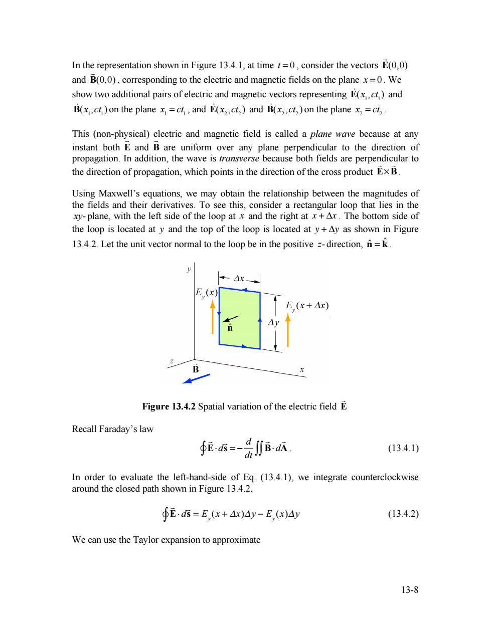
In the representation shown in Figure 13.4.1,at time=0,consider the vectors E(0,0) and B(0,0),corresponding to the electric and magnetic fields on the plane x=0.We show two additional pairs of electric and magnetic vectors representing E(x)and B(xc on the plane x=c,and E(x2,ct2)and B(x2ct)on the plane x2=cl2 This (non-physical)electric and magnetic field is called a plane wave because at any instant both E and B are uniform over any plane perpendicular to the direction of propagation.In addition,the wave is transverse because both fields are perpendicular to the direction of propagation,which points in the direction of the cross product Ex B Using Maxwell's equations,we may obtain the relationship between the magnitudes of the fields and their derivatives.To see this,consider a rectangular loop that lies in the xy-plane,with the left side of the loop at x and the right at x+Ar.The bottom side of the loop is located at y and the top of the loop is located at y+Ay as shown in Figure 13.4.2.Let the unit vector normal to the loop be in the positive =-direction,n=k E(x) E(x+△x) B Figure 13.4.2 Spatial variation of the electric field E Recall Faraday's law 6=-BA (13.4.1) In order to evaluate the left-hand-side of Eq.(13.4.1),we integrate counterclockwise around the closed path shown in Figure 13.4.2, ∮E·s=E,(x+Ax)4y-E,x)Ay (13.4.2) We can use the Taylor expansion to approximate 13-813-8 In the representation shown in Figure 13.4.1, at time t = 0 , consider the vectors ! E(0,0) and ! B(0,0) , corresponding to the electric and magnetic fields on the plane x = 0 . We show two additional pairs of electric and magnetic vectors representing ! E(x1,ct 1) and ! B(x1,ct 1) on the plane x1 = ct 1 , and ! E(x2 ,ct 2 ) and ! B(x2 ,ct 2 ) on the plane x2 = ct 2 . This (non-physical) electric and magnetic field is called a plane wave because at any instant both E ! and B ! are uniform over any plane perpendicular to the direction of propagation. In addition, the wave is transverse because both fields are perpendicular to the direction of propagation, which points in the direction of the cross product E!B ! ! . Using Maxwell’s equations, we may obtain the relationship between the magnitudes of the fields and their derivatives. To see this, consider a rectangular loop that lies in the xy- plane, with the left side of the loop at x and the right at x + !x . The bottom side of the loop is located at y and the top of the loop is located at y + !y as shown in Figure 13.4.2. Let the unit vector normal to the loop be in the positive z- direction, nˆ = kˆ . Figure 13.4.2 Spatial variation of the electric field E ! Recall Faraday’s law ! E!d ! s = " d dt ! B! d ! "# ## A . (13.4.1) In order to evaluate the left-hand-side of Eq. (13.4.1), we integrate counterclockwise around the closed path shown in Figure 13.4.2, ! E! d ! s "" = E y (x + #x)#y $ E y (x)#y (13.4.2) We can use the Taylor expansion to approximate