正在加载图片...

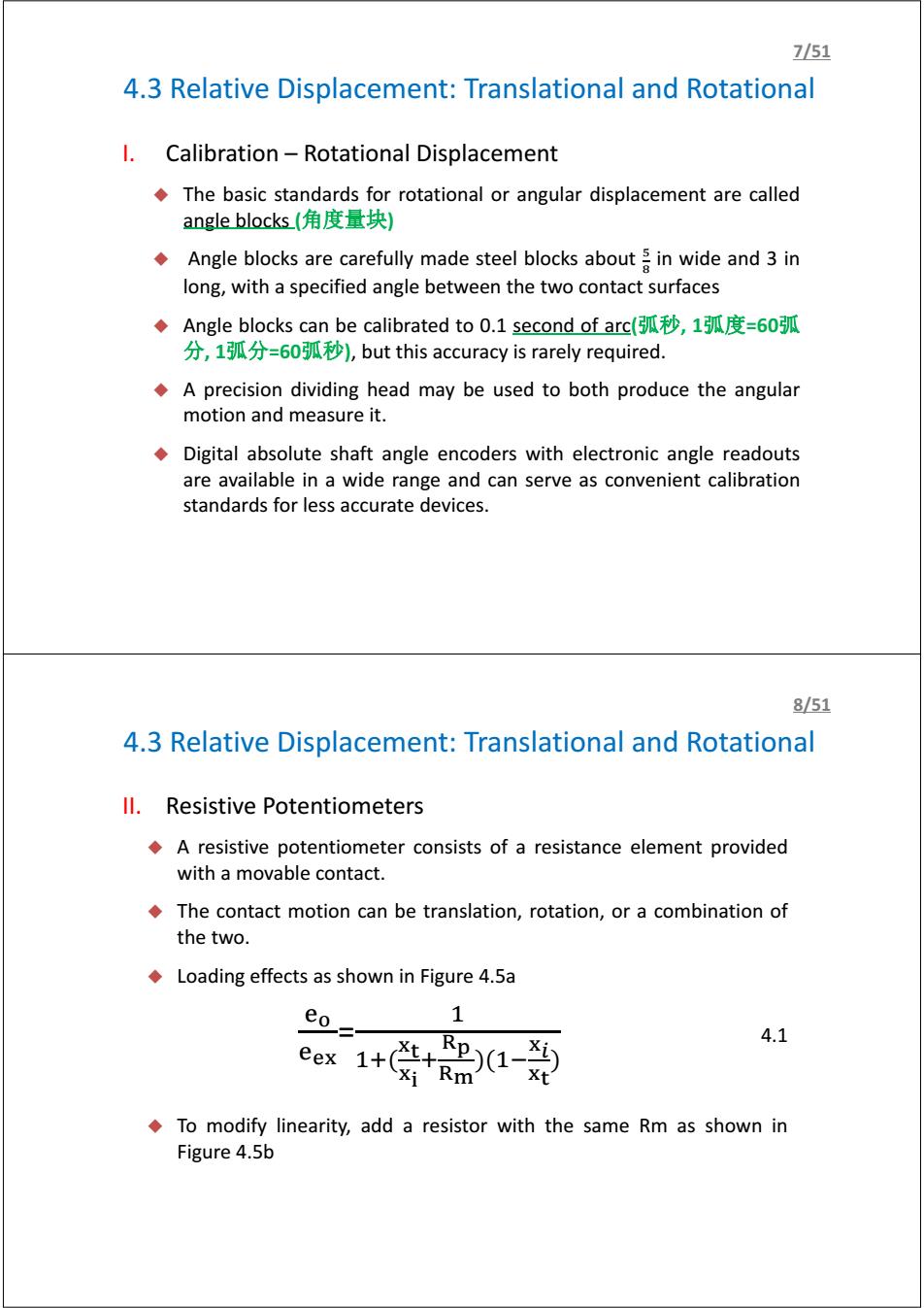
7/51 4.3 Relative Displacement:Translational and Rotational I.Calibration-Rotational Displacement The basic standards for rotational or angular displacement are called angle blocks(角度量块) Angle blocks are carefully made steel blocks about in wide and 3 in long,with a specified angle between the two contact surfaces ◆Angle blocks can be calibrated to0.1 second of arc(弧秒,1弧度=60弧 分,1弧分=60弧秒),but this accuracy is rarely required. A precision dividing head may be used to both produce the angular motion and measure it. Digital absolute shaft angle encoders with electronic angle readouts are available in a wide range and can serve as convenient calibration standards for less accurate devices. 8/51 4.3 Relative Displacement:Translational and Rotational ll.Resistive Potentiometers A resistive potentiometer consists of a resistance element provided with a movable contact. The contact motion can be translation,rotation,or a combination of the two. Loading effects as shown in Figure 4.5a e 1 eex1++01-0 4.1 xi Rm To modify linearity,add a resistor with the same Rm as shown in Figure 4.5b4.3 Relative Displacement: Translational and Rotational I. Calibration – Rotational Displacement The basic standards for rotational or angular displacement are called angle blocks (角度量块) Angle blocks are carefully made steel blocks about ఱ ఴ in wide and 3 in long, with a specified angle between the two contact surfaces Angle blocks can be calibrated to 0.1 second of arc(弧秒, 1弧度=60弧 分, 1弧分=60弧秒), but this accuracy is rarely required. A precision dividing head may be used to both produce the angular motion and measure it. Digital absolute shaft angle encoders with electronic angle readouts are available in a wide range and can serve as convenient calibration standards for less accurate devices. 7/51 4.3 Relative Displacement: Translational and Rotational II. Resistive Potentiometers A resistive potentiometer consists of a resistance element provided with a movable contact. The contact motion can be translation, rotation, or a combination of the two. Loading effects as shown in Figure 4.5a ୣ ୣ౮ = ଵ ଵା(౮౪ ౮ ା ౦ ౣ )(ଵି౮ ౮౪ ) 4.1 To modify linearity, add a resistor with the same Rm as shown in Figure 4.5b 8/51