Chapter 4 Motion Dimensional Measurement by Yixin Ma 20/03/2013 2/51 Contents: 1.Introduction 2.Fundamental Standards 3.Relative Displacement:Translational and Rotational 4.Relative Velocity:Translational and Rotational 5.Relative Acceleration Measurement 6.Seismic-(Absolute-)Acceleration Pickups (Accelerometers) 7.Calibration of Vibration Pickups 8.Jerk Pickups 9.Pendulous(Gravity-Referenced)Angular-Displacement Sensors 10.Gyroscopic (Absolute)Angular-Displacement and Velocity Sensors 11.Coordinate-Measuring Machines 12.Surface-Finish Measurement 13.Machine Vision 14.The Global-Positioning System(GPS)
Chapter 4 Motion & Dimensional Measurement by Yixin Ma 20/03/2013 Contents: 1. Introduction 2. Fundamental Standards 3. Relative Displacement: Translational and Rotational 4. Relative Velocity: Translational and Rotational 5. Relative Acceleration Measurement 6. Seismic-(Absolute-) Acceleration Pickups (Accelerometers) 7. Calibration of Vibration Pickups 8. Jerk Pickups 9. Pendulous (Gravity-Referenced) Angular-Displacement Sensors 10. Gyroscopic (Absolute) Angular-Displacement and Velocity Sensors 11. Coordinate-Measuring Machines 12. Surface-Finish Measurement 13. Machine Vision 14. The Global-Positioning System (GPS) 2/51
3/51 4.2 Fundamental Standards ·Standard Levels International National Reference Standards 一 Working Standards Interlaboratory Standards Fundamental Quantities of the International Measuring System Length,Time,Mass,Temperature ·Length -Prior to 1960,platinum(铂,白金)-iridium(铱)international Meter Bar(米棒) From 1960,1650763.73 wavelength of krypton-86(-86)lamp in specified condition 中文课本中米的定义:1米是“光在真空中于1/299792458秒的时间间隔内 所经历路程的长度”,称为“米的国际基准”。 。Time In 1956,time interval definition,by the International Committee on Weights and Measures In 1964,frequencies of atomic resonators,by metrologists Cesium Notes:1.Intent is to show benchmarks Cesium 4/51 of progress.Various clock types atomic atomic (improved 10 can show improved accuracies. NBS HI) (NBS-5 EST) 2.Prior to 1000 A.D.varied timekeepers were used such Cesium 100 as mechanical water clocks atomic nocturnials,sundials,time (NBS I) 1 us candles,etc..of little known Cesium accuracy. 10 FIRST ATOMIC CL0CK(1949) Accuracy of 100 ephemeris time Quartz crystal 型 Variations in earth's rotation rate 44444464644446/4464444444444444 Pendulum free and FREE PENDULU (SHORTT) 10 pressure constant (Riefler) 台 100 Barometric Chronometer (Harrison) compensation Robinson】 1 Temperature compensation(Graham). ●improved escapement 10- Pendulum(Huygen) (Graham) 子 Cross-beat 102 escapement hydromechanical (Burgi) 103 1973 Verge and foliot 10 1 hr balance clocks 1000 1200 1400 1600 1800 2000 Calendar years,A.D
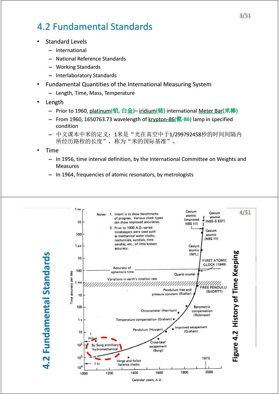
4.2 Fundamental Standards • Standard Levels – International – National Reference Standards – Working Standards – Interlaboratory Standards • Fundamental Quantities of the International Measuring System – Length, Time, Mass, Temperature • Length – Prior to 1960, platinum(铂, 白金)– iridium(铱) international Meter Bar(米棒) – From 1960, 1650763.73 wavelength of krypton-86(氪-86) lamp in specified condition – 中文课本中米的定义:1米是“光在真空中于1/299792458秒的时间间隔内 所经历路程的长度”,称为“米的国际基准”。 • Time – In 1956, time interval definition, by the International Committee on Weights and Measures – In 1964, frequencies of atomic resonators, by metrologists 3/51 苏颂及其水运仪象台 4.2 Fundamental Standards Figure 4.2 History of Time Keeping 4/51
5/51 4.3 Relative Displacement:Translational and Rotational I. Calibration ll.Resistive Potentiometers Ill.Resistance Strain Gage IV.Differential Transformers V.Synchros and Resolvers VI.Variable-Inductance Variable-Reluctance Pickups VIl.Eddy-Current Noncontacting Transducers VIll.Capacitance Pickups IX.Piezoelectric Transducers X.Electro-Optical Devices XI.Photographic and Electronic-Imaging Techniques XIl.Photoelastic,Brittle-Coating,and Moir Fringe Stress-Analysis Techniques XIll.Displacement-to-Pressure(Nozzle-Flapper)Transducer XIV.Digital Displacement Transducers(Translational and Rotary Encoders) XV.Ultrasonic Transducers 6/51 4.3 Relative Displacement:Translational and Rotational I.Calibration-Translational Displacement Translation:a uniform movement without rotation ◆Static calibration of translational平移/平动)devices using micrometers(千分尺)usually has accuracy of0.01mm ◆Using level(杠杆)devices or wedge-type(楔形)mechanisms for motion reduction to achieve smaller resolution ◆Using linear encoder(编码器)scales or laser interferometers(千涉仪)to realize greater accuracy ◆Gage Blocks(量块:small blocks of hard,dimensionally stable steel or other material made in sets that can be stacked to provide accurate dimension over a wide range and in small steps. When transducers are calibrated to very high accuracy,it is extremely important to control all interfering and/or modifying inputs such as ambient temperature,electrical excitation to the transducer,etc
4.3 Relative Displacement: Translational and Rotational I. Calibration II. Resistive Potentiometers III. Resistance Strain Gage IV. Differential Transformers V. Synchros and Resolvers VI. Variable-Inductance & Variable-Reluctance Pickups VII. Eddy-Current Noncontacting Transducers VIII. Capacitance Pickups IX. Piezoelectric Transducers X. Electro-Optical Devices XI. Photographic and Electronic-Imaging Techniques XII. Photoelastic, Brittle-Coating, and Moir Fringe Stress-Analysis Techniques XIII. Displacement-to-Pressure (Nozzle-Flapper) Transducer XIV. Digital Displacement Transducers (Translational and Rotary Encoders) XV. Ultrasonic Transducers 5/51 4.3 Relative Displacement: Translational and Rotational I. Calibration – Translational Displacement Translation: a uniform movement without rotation Static calibration of translational( 平 移 / 平 动 ) devices using micrometers(千分尺) usually has accuracy of 0.01mm Using level(杠杆) devices or wedge-type(楔形) mechanisms for motion reduction to achieve smaller resolution Using linear encoder(编码器) scales or laser interferometers (干涉仪) to realize greater accuracy Gage Blocks (量块): small blocks of hard, dimensionally stable steel or other material made in sets that can be stacked to provide accurate dimension over a wide range and in small steps. When transducers are calibrated to very high accuracy, it is extremely important to control all interfering and/or modifying inputs such as ambient temperature, electrical excitation to the transducer, etc. 6/51
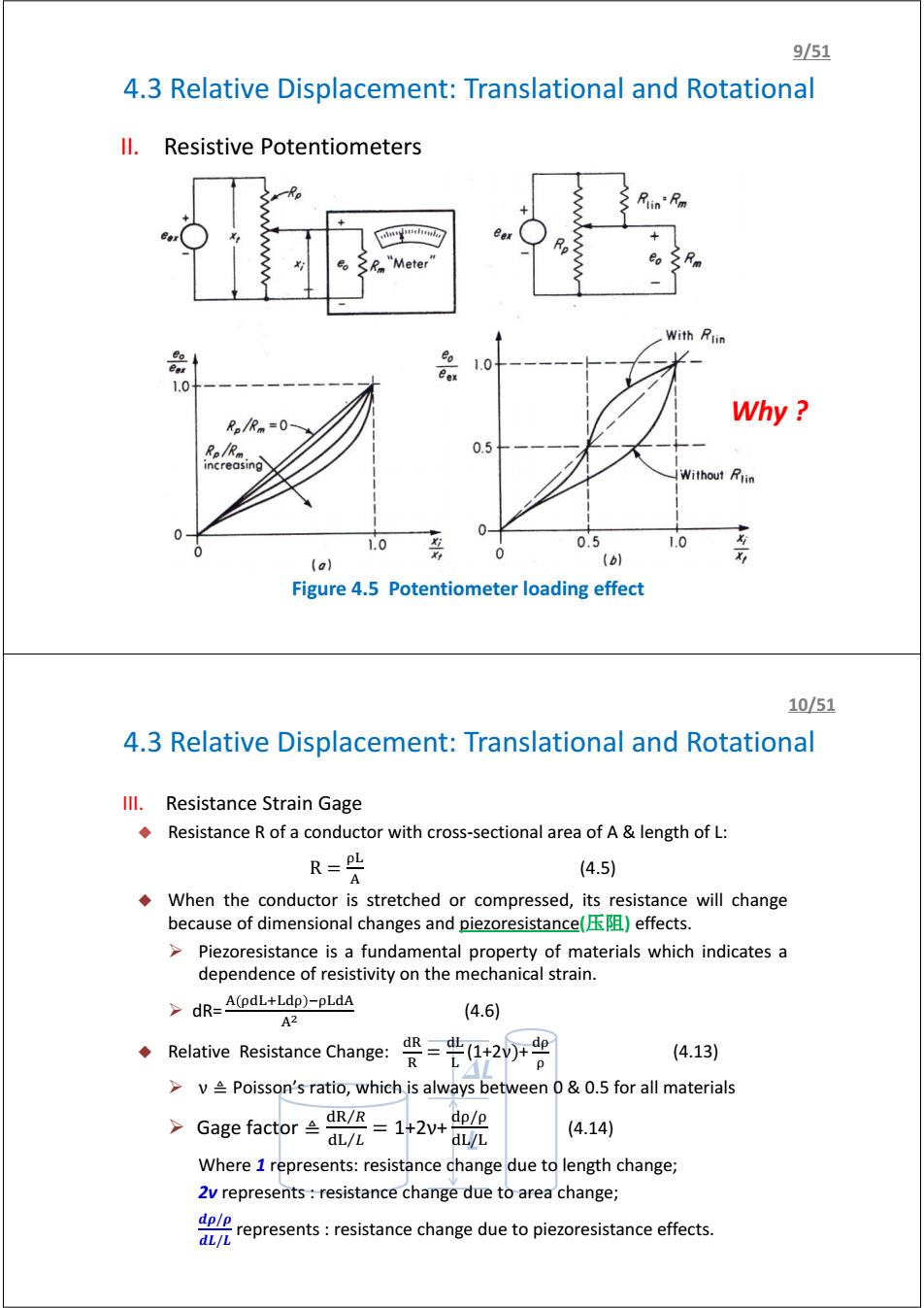
7/51 4.3 Relative Displacement:Translational and Rotational I.Calibration-Rotational Displacement The basic standards for rotational or angular displacement are called angle blocks(角度量块) Angle blocks are carefully made steel blocks about in wide and 3 in long,with a specified angle between the two contact surfaces ◆Angle blocks can be calibrated to0.1 second of arc(弧秒,1弧度=60弧 分,1弧分=60弧秒),but this accuracy is rarely required. A precision dividing head may be used to both produce the angular motion and measure it. Digital absolute shaft angle encoders with electronic angle readouts are available in a wide range and can serve as convenient calibration standards for less accurate devices. 8/51 4.3 Relative Displacement:Translational and Rotational ll.Resistive Potentiometers A resistive potentiometer consists of a resistance element provided with a movable contact. The contact motion can be translation,rotation,or a combination of the two. Loading effects as shown in Figure 4.5a e 1 eex1++01-0 4.1 xi Rm To modify linearity,add a resistor with the same Rm as shown in Figure 4.5b
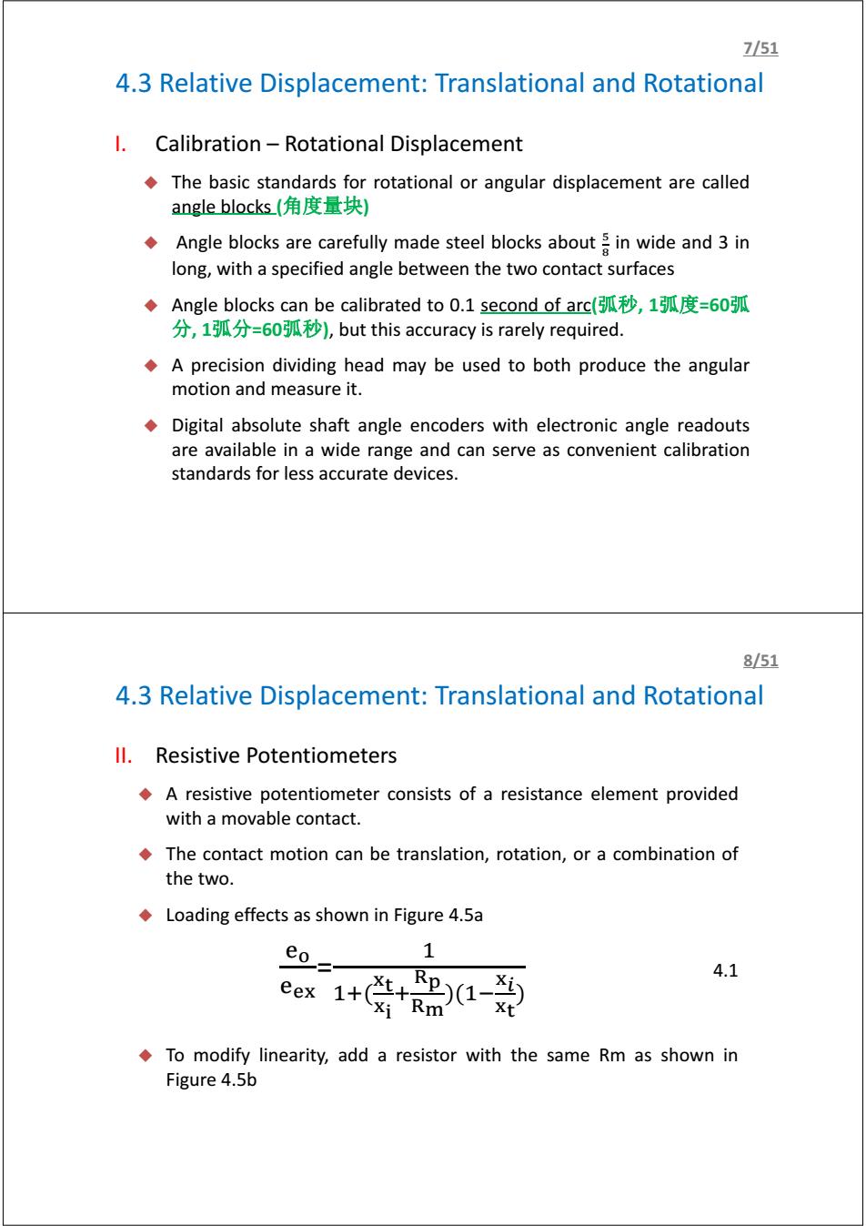
4.3 Relative Displacement: Translational and Rotational I. Calibration – Rotational Displacement The basic standards for rotational or angular displacement are called angle blocks (角度量块) Angle blocks are carefully made steel blocks about ఱ ఴ in wide and 3 in long, with a specified angle between the two contact surfaces Angle blocks can be calibrated to 0.1 second of arc(弧秒, 1弧度=60弧 分, 1弧分=60弧秒), but this accuracy is rarely required. A precision dividing head may be used to both produce the angular motion and measure it. Digital absolute shaft angle encoders with electronic angle readouts are available in a wide range and can serve as convenient calibration standards for less accurate devices. 7/51 4.3 Relative Displacement: Translational and Rotational II. Resistive Potentiometers A resistive potentiometer consists of a resistance element provided with a movable contact. The contact motion can be translation, rotation, or a combination of the two. Loading effects as shown in Figure 4.5a ୣ ୣ౮ = ଵ ଵା(౮౪ ౮ ା ౦ ౣ )(ଵି౮ ౮౪ ) 4.1 To modify linearity, add a resistor with the same Rm as shown in Figure 4.5b 8/51
951 4.3 Relative Displacement:Translational and Rotational ll.Resistive Potentiometers Rlin'Fm "Meter With Rtin 品 Bex 1.0 1.0 Why Re/Rm=0- R。R。 0.5 increasing Without Rlin 1.0 0.5 1.0 0 (a) (b) Figure 4.5 Potentiometer loading effect 10/51 4.3 Relative Displacement:Translational and Rotational Ill.Resistance Strain Gage Resistance R of a conductor with cross-sectional area of A length of L: R=PL (4.5) A When the conductor is stretched or compressed,its resistance will change because of dimensional changes and piezoresistance()effects. >Piezoresistance is a fundamental property of materials which indicates a dependence of resistivity on the mechanical strain. >dR=A(pdL+Ldp)-pLdA A2 (4.6) Relative Resistance Change: =20r号 (4.13) p >v Poisson's ratio,which is always between 0&0.5 for all materials >Ga8 efactor2=142+鼢 dL/L (4.14) Where 1 represents:resistance change due to length change; 2v represents resistance change due to area change; represets:resistance change due to piezoresistance effects. dL/L
II. Resistive Potentiometers Figure 4.5 Potentiometer loading effect 4.3 Relative Displacement: Translational and Rotational 9/51 www.vishay.com www.bourns.com Why ? 4.3 Relative Displacement: Translational and Rotational L DL III. Resistance Strain Gage Resistance R of a conductor with cross-sectional area of A & length of L: R = (4.5) When the conductor is stretched or compressed, its resistance will change because of dimensional changes and piezoresistance(压阻) effects. ¾ Piezoresistance is a fundamental property of materials which indicates a dependence of resistivity on the mechanical strain. ¾ dR= ୢାୢ ିୢ మ (4.6) Relative Resistance Change: ୢୖ ୖ = ୢ (1+2ν)+ ୢ (4.13) ¾ ν ≜ Poisson’s ratio, which is always between 0 & 0.5 for all materials ¾ Gage factor ≜ ୢୖ ோ⁄ ୢ ⁄ = 1+2ν+ ୢ/ ୢ/ (4.14) Where 1 represents: resistance change due to length change; 2ν represents : resistance change due to area change; ࣋/࣋ࢊ ࡸࢊ/ࡸ represents : resistance change due to piezoresistance effects. 10/51
11/51 4.3 Relative Displacement:Translational and Rotational Ill.Resistance Strain Gage Strain gauges have two types of majority applications: in experimental stress analysis of machines and structures; in construction of force,Torque,pressure,flow,and acceleration transducers. Seven types of implementation ways: >Unbonded metal-wire gage;---obsoleted Bonded metal-wire gage;---obsoleted Bonded metal-foil gage; Vacuum-deposited thin-metal-film gage; Sputter-deposited thin-metal film gage; Bonded semiconductor gage; Diffused semiconductor gage. 12/51 4.3 Relative Displacement:Translational and Rotational Ill.Resistance Strain Gage Input motion 1,2,3,4 are preloaded strain wires (Electrical connections not shown) R Wire length is of the Flexure plate order of I in.or less Fixed base Figure 4.10 Unbonded strain gage
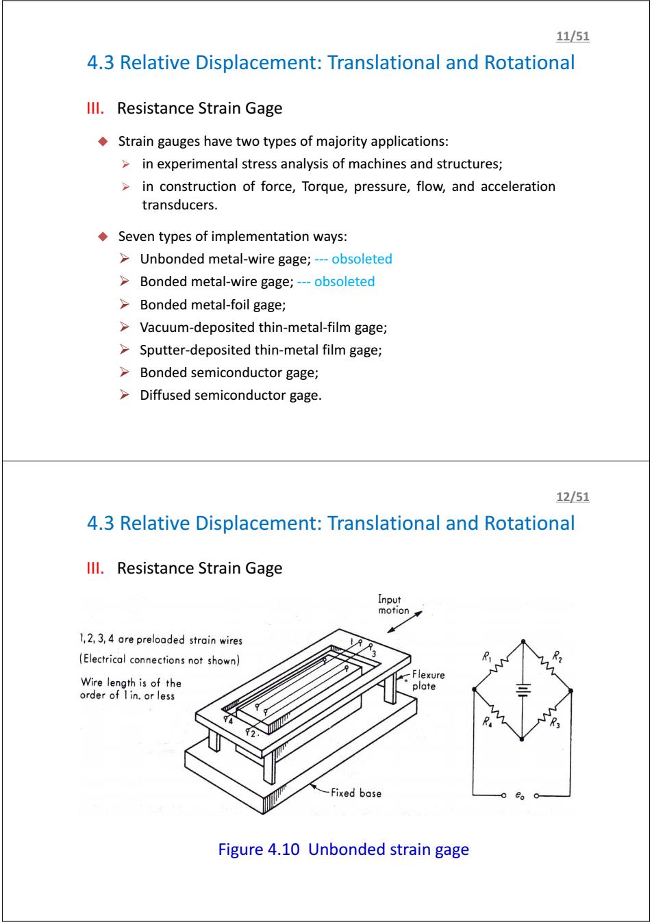
4.3 Relative Displacement: Translational and Rotational III. Resistance Strain Gage Strain gauges have two types of majority applications: ¾ in experimental stress analysis of machines and structures; ¾ in construction of force, Torque, pressure, flow, and acceleration transducers. Seven types of implementation ways: ¾ Unbonded metal-wire gage; --- obsoleted ¾ Bonded metal-wire gage; --- obsoleted ¾ Bonded metal-foil gage; ¾ Vacuum-deposited thin-metal-film gage; ¾ Sputter-deposited thin-metal film gage; ¾ Bonded semiconductor gage; ¾ Diffused semiconductor gage. 11/51 4.3 Relative Displacement: Translational and Rotational III. Resistance Strain Gage Figure 4.10 Unbonded strain gage 12/51
1351 4.3 Relative Displacement:Translational and Rotational Ill.Resistance Strain Gage Figure 4.11 Foil Strain gage 14/51 4.3 Relative Displacement:Translational and Rotational Ill.Resistance Strain Gage http://en.wikipedia.org/wiki/Strain_gauge
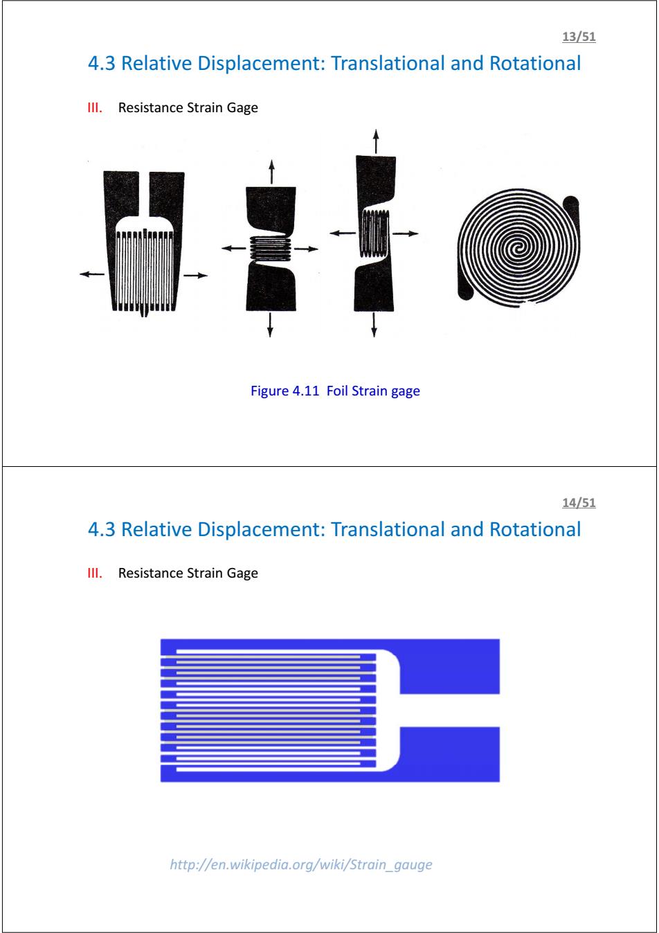
4.3 Relative Displacement: Translational and Rotational III. Resistance Strain Gage Figure 4.11 Foil Strain gage 13/51 4.3 Relative Displacement: Translational and Rotational III. Resistance Strain Gage http://en.wikipedia.org/wiki/Strain_gauge 14/51
15/51 4.3 Relative Displacement:Translational and Rotational Ill.Resistance Strain Gage Active gage % 0 Fixed resistors Load Dummy gage Some material at same temperature Figure 4.13 Strain-gage Temperature Compensation Application Example:Strain rate-dependent tensile properties and dynamic electromechanical response of carbon nanotube fibers 16/51 4.3 Relative Displacement:Translational and Rotational Ill.Resistance Strain Gage Stainless steel Highly compacted (补偿细丝) (高度压缩的 strain tube magnesium oxide powder Dummy filament 氧化镁粉末) 77 Active Stainless steel filament mounting flange (工作细丝) (不锈钢 安装法兰) Specimen 样品;样本) Strain tube Figure 4.16 Flange Hermetically(气密的) Specimen sealed,weldable strain gage for sever environment
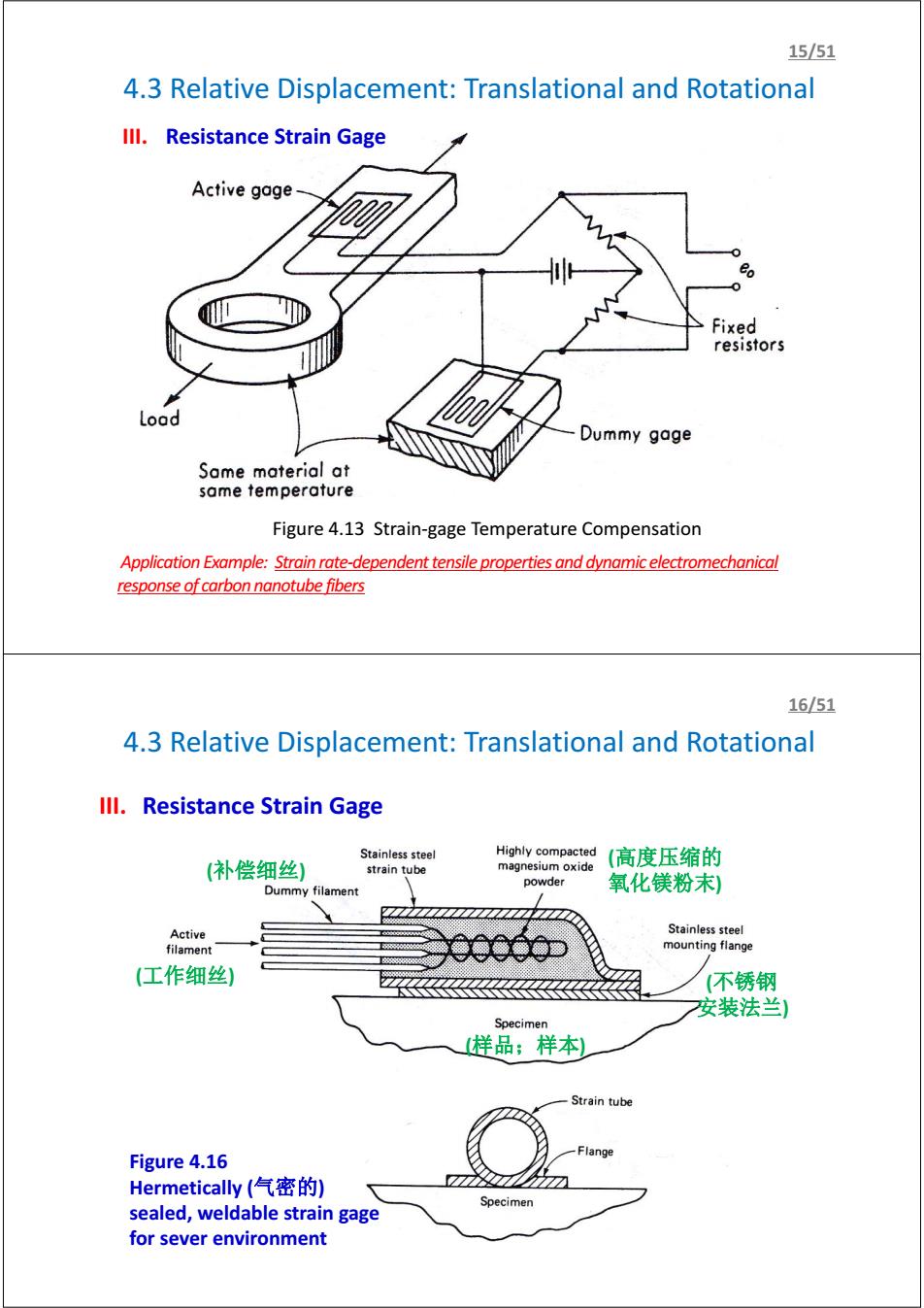
4.3 Relative Displacement: Translational and Rotational III. Resistance Strain Gage Figure 4.13 Strain-gage Temperature Compensation 15/51 Application Example: Strain rate-dependent tensile properties and dynamic electromechanical response of carbon nanotube fibers 4.3 Relative Displacement: Translational and Rotational (样品;样本) (工作细丝) (高度压缩的 氧化镁粉末) (不锈钢 安装法兰) (补偿细丝) III. Resistance Strain Gage Figure 4.16 Hermetically (气密的) sealed, weldable strain gage for sever environment 16/51
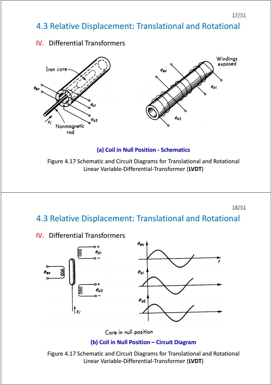
17/51 4.3 Relative Displacement:Translational and Rotational IV.Differential Transformers Windings exposed Iron core eo2 Nonmagnetic rod (a)Coil in Null Position-Schematics Figure 4.17 Schematic and Circuit Diagrams for Translational and Rotational Linear Variable-Differential-Transformer(LVDT) 18/51 4.3 Relative Displacement:Translational and Rotational IV.Differential Transformers eol 0+ eo2 0= Core in null position (b)Coil in Null Position-Circuit Diagram Figure 4.17 Schematic and Circuit Diagrams for Translational and Rotational Linear Variable-Differential-Transformer(LVDT)
4.3 Relative Displacement: Translational and Rotational IV. Differential Transformers (a) Coil in Null Position - Schematics Figure 4.17 Schematic and Circuit Diagrams for Translational and Rotational Linear Variable-Differential-Transformer (LVDT) 17/51 4.3 Relative Displacement: Translational and Rotational IV. Differential Transformers (b) Coil in Null Position – Circuit Diagram Figure 4.17 Schematic and Circuit Diagrams for Translational and Rotational Linear Variable-Differential-Transformer (LVDT) 18/51

1951 4.3 Relative Displacement:Translational and Rotational IV.Differential Transformers 。+ eo Core above null 20 Core at null Core below null (c)Series Opposing Secondaries Figure 4.17 Schematic and Circuit Diagrams for Translational and Rotational Linear Variable-Differential-Transformer(LVDT) 20/51 4.3 Relative Displacement:Translational and Rotational IV.Differential Transformers Specially shaped iron form ● 00000 Linear for limited rotation eex (-40°<日<+40) (e)Rotational Differential Transformer Figure 4.17 Schematic and Circuit Diagrams for Translational and Rotational Linear Variable-Differential-Transformer (LVDT)
4.3 Relative Displacement: Translational and Rotational IV. Differential Transformers (c) Series Opposing Secondaries Figure 4.17 Schematic and Circuit Diagrams for Translational and Rotational Linear Variable-Differential-Transformer (LVDT) 19/51 4.3 Relative Displacement: Translational and Rotational IV. Differential Transformers (e) Rotational Differential Transformer Figure 4.17 Schematic and Circuit Diagrams for Translational and Rotational Linear Variable-Differential-Transformer (LVDT) 20/51