Chapter 11 Data Transmission and Instrument Connectivity by Yixin Ma 22/05/2013 2/18 CONTENTS 11.1 Cable Transmission of Analog Voltage and Current Signals 11.2 Cable Transmission of Digital Data 11.3 Fiber-Optic Data Transmission 11.4 Radio Telemetry 11.5 Pneumatic Transmission 11.6 Synchro Position Repeater Systems 11.7 Slip Rings and Rotary Transformers 11.8 Instrument Connectivity 11.9 Data Storage with Delayed Playback (an Alternative to Data Transmission)
Chapter 11 Data Transmission and Instrument Connectivity by Yixin Ma 22/05/2013 CONTENTS 11.1 Cable Transmission of Analog Voltage and Current Signals 11.2 Cable Transmission of Digital Data 11.3 Fiber-Optic Data Transmission 11.4 Radio Telemetry 11.5 Pneumatic Transmission 11.6 Synchro Position Repeater Systems 11.7 Slip Rings and Rotary Transformers 11.8 Instrument Connectivity 11.9 Data Storage with Delayed Playback (an Alternative to Data Transmission) 2/18
/18 11.1 Cable Transmission of Analog Voltage and Current Signals Cable transmission:generally a simple cable is used to transmit an analog voltage/current signal from one location to another. Analysis of a cable or transmission line:uses distributed-parameter (partial differential equation)approach since the properties of resistance, inductance,and capacitance are not lumped or localized. Typical resistance per foot might be of the order of 0.012 and capacitance of 30pF/ft. 000 000o 8 series resistance per unit length Infinitesimal length series inductonce per unit length of cable ge shunt conductance per unit length c shunt capocitance per unit length Figure 11.1a The Model Generally Employed for Cable Analysis 11.1 Cable Transmission of Analog Voltage and Current Signal R/2 /2 R/2 /2 0000000 eo (6) (e) Figure 11.1 (b)Lumped network which is an approximation suitable for low frequencies. (c)Crude model used when frequencies are not too high and cable lengths are not too long
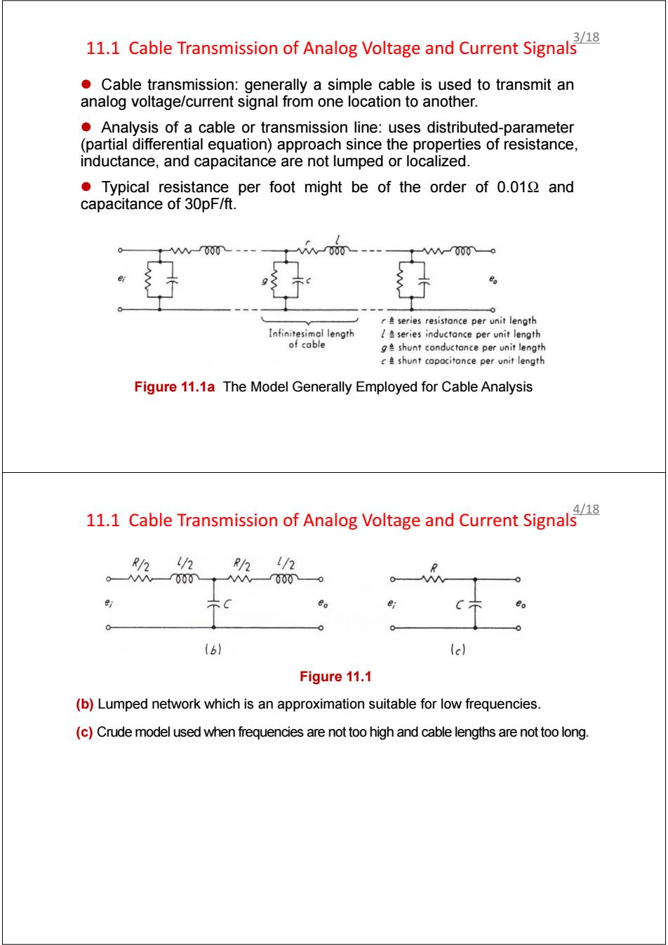
11.1 Cable Transmission of Analog Voltage and Current Signals z Cable transmission: generally a simple cable is used to transmit an analog voltage/current signal from one location to another. z Analysis of a cable or transmission line: uses distributed-parameter (partial differential equation) approach since the properties of resistance, inductance, and capacitance are not lumped or localized. z Typical resistance per foot might be of the order of 0.01Ω and capacitance of 30pF/ft. Figure 11.1a The Model Generally Employed for Cable Analysis 3/18 11.1 Cable Transmission of Analog Voltage and Current Signals Figure 11.1 (b) Lumped network which is an approximation suitable for low frequencies. (c) Crude model used when frequencies are not too high and cable lengths are not too long. 4/18
11.1 Cable Transmission of Analog Voltage and Current Signals 10.000 ft of cable 是t 1.5- 1.0 10 1001,000 10,000100,000 Frequency, w Hz R=100,000ohms -100° -200° (d) -300° |会wl叶 1.0 0.8 =100 ohms 0.6 =300 ohms 7000 ft of cable 0.4 voltage source 0.2 =1,000ohms internal resistance 0 R=100,000ohms 10 le] 100 1,000 10,000 Frequency,Hz Figure 11.1d e:some typical simulation results. /18 11.1 Cable Transmission of Analog Voltage and Current Signals Current loop:a hard-wired (cable)data-transmission technique widely utilized in the process industries,usually a 4-to 20-mA range. Transmitters are available which convert millivolt,thermocouple,RTD frequency,slidewire potentiometer,or bridge-circuit inputs into a proportional output current.Fig.11.2 shows the. Ac line power Up to 10,000 ft required at this end only 80-Vsystem power supply A 4 to 20 mA 4 to 20 mA Line Digital current resistance ammeter transmitter Thermo couple Figure 11.2 Remote sensor site The Two-wire Version Central control room Current Loop of 4 to 20mA The transmitter is a true current source,which makes the system relative immune to induced noise voltages and line resistance changes (within the 3550 limit)
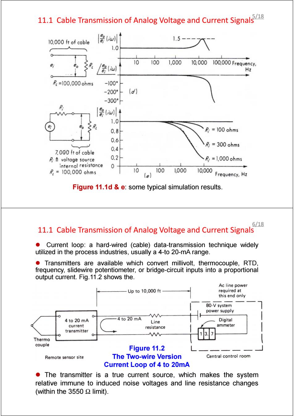
11.1 Cable Transmission of Analog Voltage and Current Signals Figure 11.1d & e: some typical simulation results. 5/18 11.1 Cable Transmission of Analog Voltage and Current Signals z Current loop: a hard-wired (cable) data-transmission technique widely utilized in the process industries, usually a 4-to 20-mA range. z Transmitters are available which convert millivolt, thermocouple, RTD, frequency, slidewire potentiometer, or bridge-circuit inputs into a proportional output current. Fig.11.2 shows the. Figure 11.2 The Two-wire Version Current Loop of 4 to 20mA z The transmitter is a true current source, which makes the system relative immune to induced noise voltages and line resistance changes (within the 3550 Ω limit). 6/18
7/18 11.2 Cable Transmission of Digital Data When data must be transmitted very long distances (100 mi is not unusual),analog signals tend to be corrupted by the response characteristics of the transmission line and pickup of spurious noise voltages from a number of sources. Under such conditions,it may be desirable to convert the analog signal to some digital form,transmit them in digital form,and then reconvert to analog form if desired. ●Vhy digital?? -The size or precise shape of a pulse in a digital system is not particularly important. -The system operates on the presence or absence of some sort of pulse. -Even rather severe degradation(L.degre'defn,毁坏,恶化)of pulse shape by the transmission medium does not affect the accuracy of a digital system as long as the presence or absence of a pulse can be detected. 8/18 11.3 Fiber-Optic Data Transmission Fiber optics offers wide bandwidths and high data rates while avoiding many of the interference and security constraints associated with traditional electronic communications. -Provides high isolation:glass cable can carry signals to or from instrumentation at high common-mode voltage levels without creating electrical paths between devices. -Immune to electromagnetic interference from sources such as lightning or power switching -Provide good noise rejection -Produce no sparks
11.2 Cable Transmission of Digital Data z When data must be transmitted very long distances (100 mi is not unusual), analog signals tend to be corrupted by the response characteristics of the transmission line and pickup of spurious noise voltages from a number of sources. z Under such conditions, it may be desirable to convert the analog signal to some digital form, transmit them in digital form, and then reconvert to analog form if desired. z Why digital? - The size or precise shape of a pulse in a digital system is not particularly important. - The system operates on the presence or absence of some sort of pulse. - Even rather severe degradation([ˌdeɡrəˈdeɪʃn],毁坏, 恶化) of pulse shape by the transmission medium does not affect the accuracy of a digital system as long as the presence or absence of a pulse can be detected. 7/18 11.3 Fiber-Optic Data Transmission z Fiber optics offers wide bandwidths and high data rates while avoiding many of the interference and security constraints associated with traditional electronic communications. - Provides high isolation: glass cable can carry signals to or from instrumentation at high common-mode voltage levels without creating electrical paths between devices. - Immune to electromagnetic interference from sources such as lightning or power switching - Provide good noise rejection. - Produce no sparks. 8/18
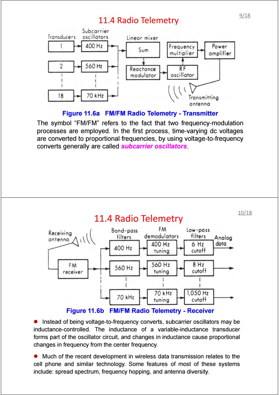
9/18 11.4 Radio Telemetry Subcarrier Transducers oscillators Linear mixer 1 400Hz Sum Frequency Power multiplier amplifier 2 560H Reactance RF modulator oscillator 18 70 kHz Transmitting antenna Figure 11.6a FM/FM Radio Telemetry -Transmitter The symbol "FM/FM"refers to the fact that two frequency-modulation processes are employed.In the first process,time-varying dc voltages are converted to proportional frequencies,by using voltage-to-frequency converts generally are called subcarrier oscillators. 10/18 11.4 Radio Telemetry Band-pass FM Receiving Low-pass demodulators antenna filters filters Analog data 400H2 400Hz 6 Hz tuning cutoff FM 560Hz 560Hz 8Hz receiver tuning cutoff 70 kHz 1,050Hz 70 kHz tuning cutoff Figure 11.6b FM/FM Radio Telemetry -Receiver Instead of being voltage-to-frequency converts,subcarrier oscillators may be inductance-controlled.The inductance of a variable-inductance transducer forms part of the oscillator circuit,and changes in inductance cause proportional changes in frequency from the center frequency. Much of the recent development in wireless data transmission relates to the cell phone and similar technology.Some features of most of these systems include:spread spectrum,frequency hopping,and antenna diversity
11.4 Radio Telemetry Figure 11.6a FM/FM Radio Telemetry - Transmitter The symbol “FM/FM” refers to the fact that two frequency-modulation processes are employed. In the first process, time-varying dc voltages are converted to proportional frequencies, by using voltage-to-frequency converts generally are called subcarrier oscillators. 9/18 11.4 Radio Telemetry Figure 11.6b FM/FM Radio Telemetry - Receiver z Instead of being voltage-to-frequency converts, subcarrier oscillators may be inductance-controlled. The inductance of a variable-inductance transducer forms part of the oscillator circuit, and changes in inductance cause proportional changes in frequency from the center frequency. z Much of the recent development in wireless data transmission relates to the cell phone and similar technology. Some features of most of these systems include: spread spectrum, frequency hopping, and antenna diversity. 10/18
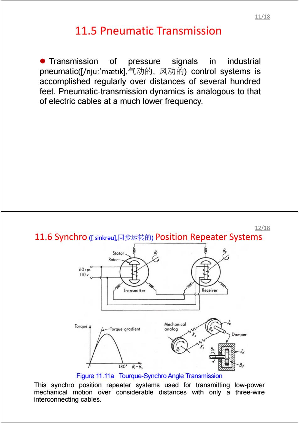
11/18 11.5 Pneumatic Transmission Transmission of pressure signals in i industrial pneumatic(/nju:'maetik],气动的,风s动的)control systems is accomplished regularly over distances of several hundred feet.Pneumatic-transmission dynamics is analogous to that of electric cables at a much lower frequency. 12/18 11.6 Synchro('sinkrau,]同步运转的)Position Repeater Systems Stator Rotor 60cps° 110v Tronsmitter Receiver Torque Mechanical Torque gradient analog Damper 1809-9 Figure 11.11a Tourque-Synchro Angle Transmission This synchro position repeater systems used for transmitting low-power mechanical motion over considerable distances with only a three-wire interconnecting cables
11.5 Pneumatic Transmission z Transmission of pressure signals in industrial pneumatic([/njuːˈmætɪk],气动的, 风动的) control systems is accomplished regularly over distances of several hundred feet. Pneumatic-transmission dynamics is analogous to that of electric cables at a much lower frequency. 11/18 11.6 Synchro ([ˈsinkrəu],同步运转的) Position Repeater Systems Figure 11.11a Tourque-Synchro Angle Transmission This synchro position repeater systems used for transmitting low-power mechanical motion over considerable distances with only a three-wire interconnecting cables. 12/18
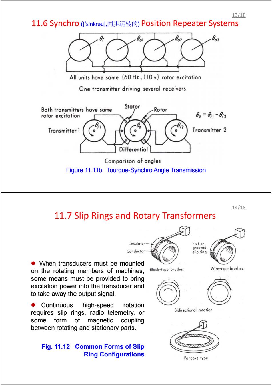
13/18 11.6 Synchro('sinkrau],同步运转的)Position Repeater Systems o2 8o1 All units hove same (60 Hz,110 v)rotor excitation One transmitter driving several receivers Both transmitters have same Stator -Rotor rotor excitotion 8。=n-82 Transmitter Transmitter 2 Differential Comparison of angles Figure 11.11b Tourque-Synchro Angle Transmission 14/18 11.7 Slip Rings and Rotary Transformers Insulator- Flat or grooved Conductor slip ring When transducers must be mounted on the rotating members of machines, Block-type brushes Wire-type brushes some means must be provided to bring excitation power into the transducer and to take away the output signal. Continuous high-speed rotation requires slip rings,radio telemetry,or Bidirectional rotation some form of magnetic coupling between rotating and stationary parts. Fig.11.12 Common Forms of Slip Ring Configurations Pancake type
11.6 Synchro ([ˈsinkrəu],同步运转的) Position Repeater Systems Figure 11.11b Tourque-Synchro Angle Transmission 13/18 11.7 Slip Rings and Rotary Transformers z When transducers must be mounted on the rotating members of machines, some means must be provided to bring excitation power into the transducer and to take away the output signal. z Continuous high-speed rotation requires slip rings, radio telemetry, or some form of magnetic coupling between rotating and stationary parts. Fig. 11.12 Common Forms of Slip Ring Configurations 14/18

15/18 11.8 Instrument connectivity In addition to connecting sensors to various signal processing devices,we also often want to interconnect "stand-alone"instruments (digital multimeters,frequency counters,etc.)to each other and to computers. A bus is usually considered to have a set of unbroken signals lines that carry digital data in parallel(rather than serial)fashion;instruments are connected by "tapping into"the bus at various locations. Communication Standards: 1.RS232(COM),RS485 2.USB(Universal Serial Bus) 3.Ethernet 4.IEEE1394(Firewire) 5.GPIB(IEEE-488.2)=General Purpose Interface Bus. 6.Parallel Port RF/Coaxial Connectors: BNC,SMA/SMB/SMC,TNC,N Type,etc. 16/18 11.8 Instrument connectivity Intemet application Corporate facility Remote manufacturing facility 00 Workstations,PCs= Ethernet GPIB-ENET/100 GPIB devices GPIB-ENET/100 GPIB devices Ethernet GPIB-ENET/100 GPIB devices Intranet application Figure 11.16 GPIB Data Transmission System
11.8 Instrument connectivity z In addition to connecting sensors to various signal processing devices, we also often want to interconnect “stand-alone” instruments (digital multimeters, frequency counters, etc.) to each other and to computers. z A bus is usually considered to have a set of unbroken signals lines that carry digital data in parallel (rather than serial) fashion; instruments are connected by “tapping into” the bus at various locations. z Communication Standards: 1. RS232 (COM), RS 485 2. USB (Universal Serial Bus) 3. Ethernet 4. IEEE1394 (Firewire) 5. GPIB (IEEE-488.2) = General Purpose Interface Bus. 6. Parallel Port z RF/Coaxial Connectors: BNC, SMA/SMB/SMC, TNC, N Type, etc. 15/18 11.8 Instrument connectivity Figure 11.16 GPIB Data Transmission System 16/18
17/18 11.9 Data storage with delayed playback an alternative to data transmission) When real-time data transmission is not required,difficult transmission problems can sometimes be avoided by using the technique of Data storage with delayed playback.For example: -Obtaining a temperature/time history for the contents of a can of food product as it passes through the processing line. Similar loggers are widely used to study the shock/vibration environment of various(truck,ship,aircraft,rail). 18/18 Assignments 1.Surf internet or reference books to find out the maximum data transfer rate and maximum data transfer length for the following Communication Standards: ①RS232(COM),RS485 2 USB(Universal Serial Bus) ③Ethernet ④lEEE1394(Firewire) 5 GPIB(IEEE-488.2)=General Purpose Interface Bus. ⑥Parallel Port 2.Surf internet or reference books to find out the feature of the following RF/Coaxial connectors,and if any other connector types that you know or you can find. Thanks for Your Attention
11.9 Data storage with delayed playback ( an alternative to data transmission) z When real-time data transmission is not required, difficult transmission problems can sometimes be avoided by using the technique of Data storage with delayed playback. For example: - Obtaining a temperature/time history for the contents of a can of food product as it passes through the processing line. - Similar loggers are widely used to study the shock/vibration environment of various(truck, ship, aircraft, rail). 17/18 Assignments 1. Surf internet or reference books to find out the maximum data transfer rate and maximum data transfer length for the following Communication Standards: ① RS232 (COM), RS 485 ② USB (Universal Serial Bus) ③ Ethernet ④ IEEE1394 (Firewire) ⑤ GPIB (IEEE-488.2) = General Purpose Interface Bus. ⑥ Parallel Port 2. Surf internet or reference books to find out the feature of the following RF/Coaxial connectors, and if any other connector types that you know or you can find. Thanks for Your Attention! 18/18