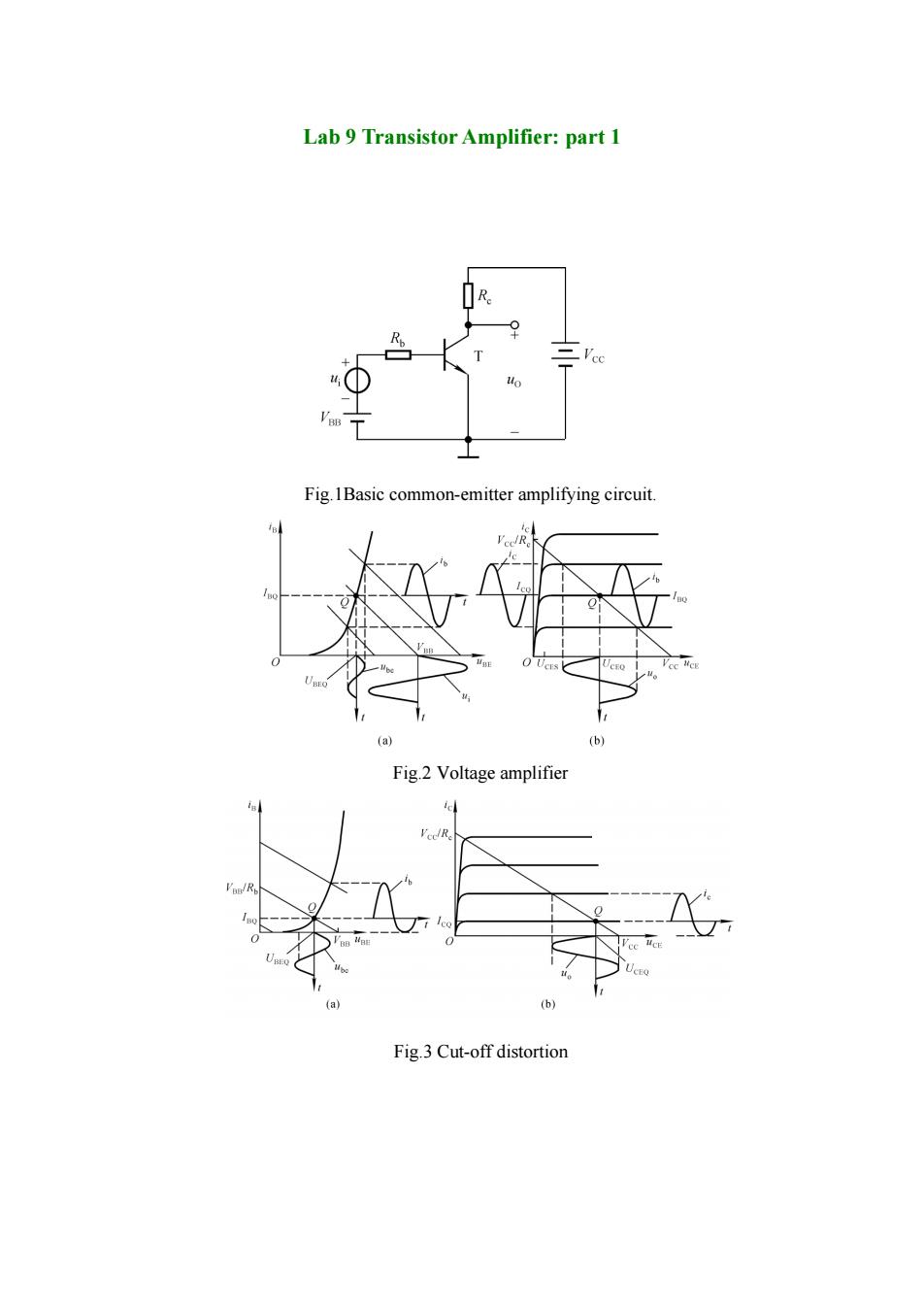
Lab 9 Transistor Amplifier:part 1 cc Fig.1Basic common-emitter amplifying circuit. (a) (b) Fig.2 Voltage amplifier cl Fig.3 Cut-off distortion
Lab 9 Transistor Amplifier: part 1 Fig.1Basic common-emitter amplifying circuit. Fig.2 Voltage amplifier Fig.3 Cut-off distortion
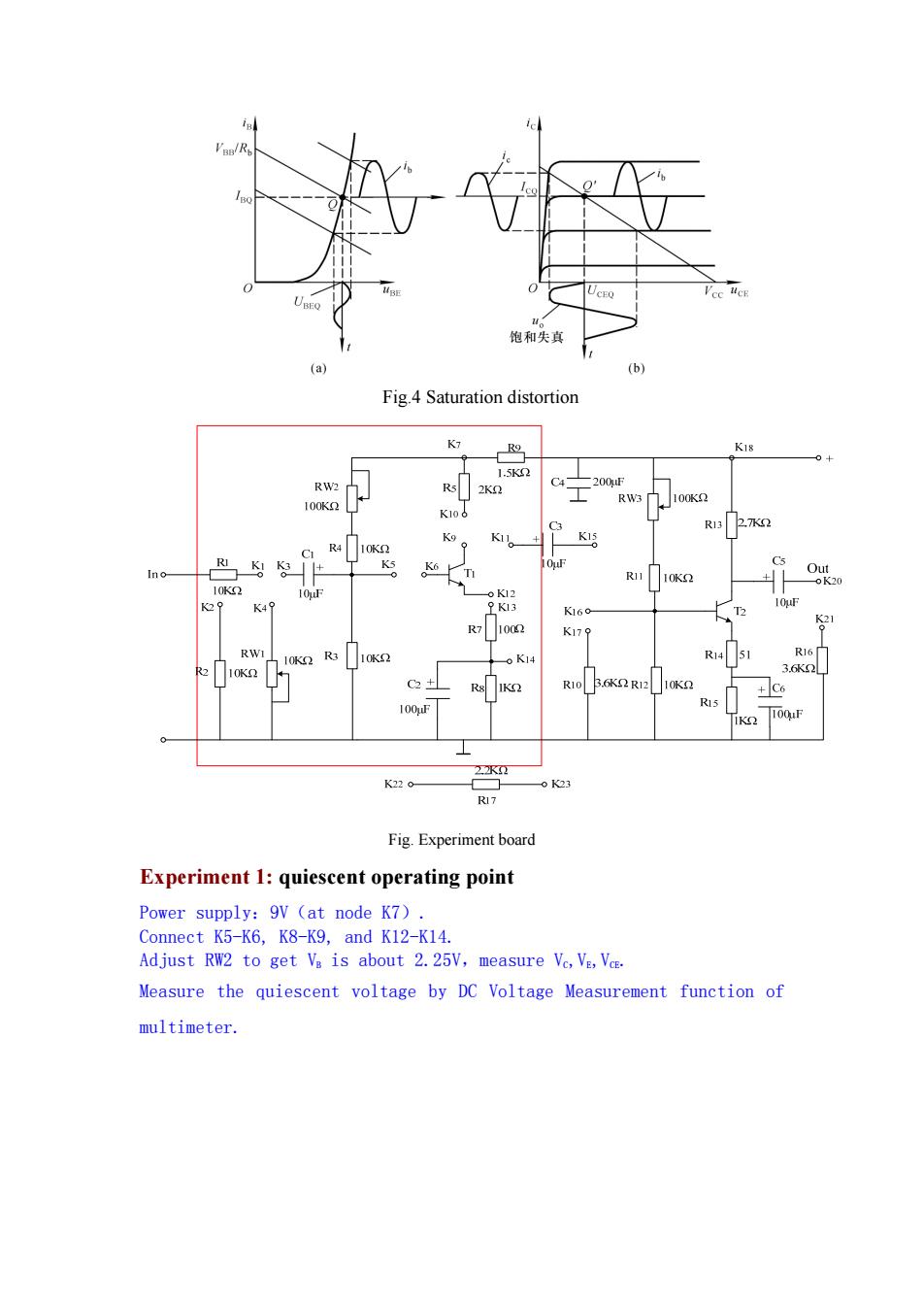
。 饱和失真 (a) (b) Fig.4 Saturation distortion K18 1.5K2 RW2 R5 C -200F RW3 100K I00K2 K106 C3 R13 2.7K2 K9 R4 K11。 10K2 RI Ks 10 C5 Ino K6 T R11 Ou 10K2 K20 10K2 o12 K49 9K13 10F K160- T2 I002 S1 K179 RWI 10K2 R3 10K2 oK14 R14 51 R16 R2 10K2 3.6K2 C2+ R10 B.6K2R12 +C6 R15 100F IK 100uF 2水☒工 K220 -o K23 R17 Fig.Experiment board Experiment 1:quiescent operating point Power supply:9V (at node K7). Connect K5-K6,K8-K9,and K12-K14. Adjust RW2 to get Va is about 2.25V,measure Vc,VE,Vce. Measure the quiescent voltage by DC Voltage Measurement function of multimeter
Fig.4 Saturation distortion Fig. Experiment board Experiment 1: quiescent operating point Power supply:9V(at node K7). Connect K5-K6, K8-K9, and K12-K14. Adjust RW2 to get VB is about 2.25V,measure VC,VE,VCE. Measure the quiescent voltage by DC Voltage Measurement function of multimeter
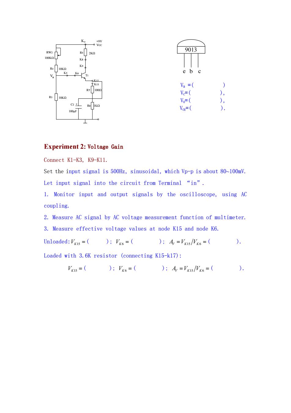
+9V RW2 9013 K5 K6 e b c K1 Va = ) 1002 V=( ), R3 V=( ), C2 Vo=( ) Experiment 2:Voltage Gain Connect K1-K3,K9-K11. Set the input signal is 500Hz,sinusoidal,which Vp-p is about 80~100mV. Let input signal into the circuit from Terminal "in". 1.Monitor input and output signals by the oscilloscope,using AC coupling. 2.Measure AC signal by AC voltage measurement function of multimeter. 3.Measure effective voltage values at node K15 and node K6. Unloaded:VKIs =)VKo=( ):A='k1s/Wk6=( ) Loaded with 3.6K resistor (connecting K15-k17): Vks=( ):Vk6=( ):A='xs/Wk6=( )
R4 10KΩ K5 K6 R3 10KΩ C2 100µF R8 1KΩ R7 100Ω K13 K12 K9 K8 R5 2KΩ + 100KΩ RW2 T1 +9V VCC VB K7 VB =( ) VC=( ), VE=( ), VCE=( ). Experiment 2: Voltage Gain Connect K1-K3, K9-K11. Set the input signal is 500Hz, sinusoidal, which Vp-p is about 80~100mV. Let input signal into the circuit from Terminal “in”. 1. Monitor input and output signals by the oscilloscope, using AC coupling. 2. Measure AC signal by AC voltage measurement function of multimeter. 3. Measure effective voltage values at node K15 and node K6. Unloaded:VK15 ( ); VK 6 ( ); AV V VKK 15 6 ( ). Loaded with 3.6K resistor (connecting K15-k17): VK15 ( ); VK 6 ( ); AV V VKK 15 6 ( )
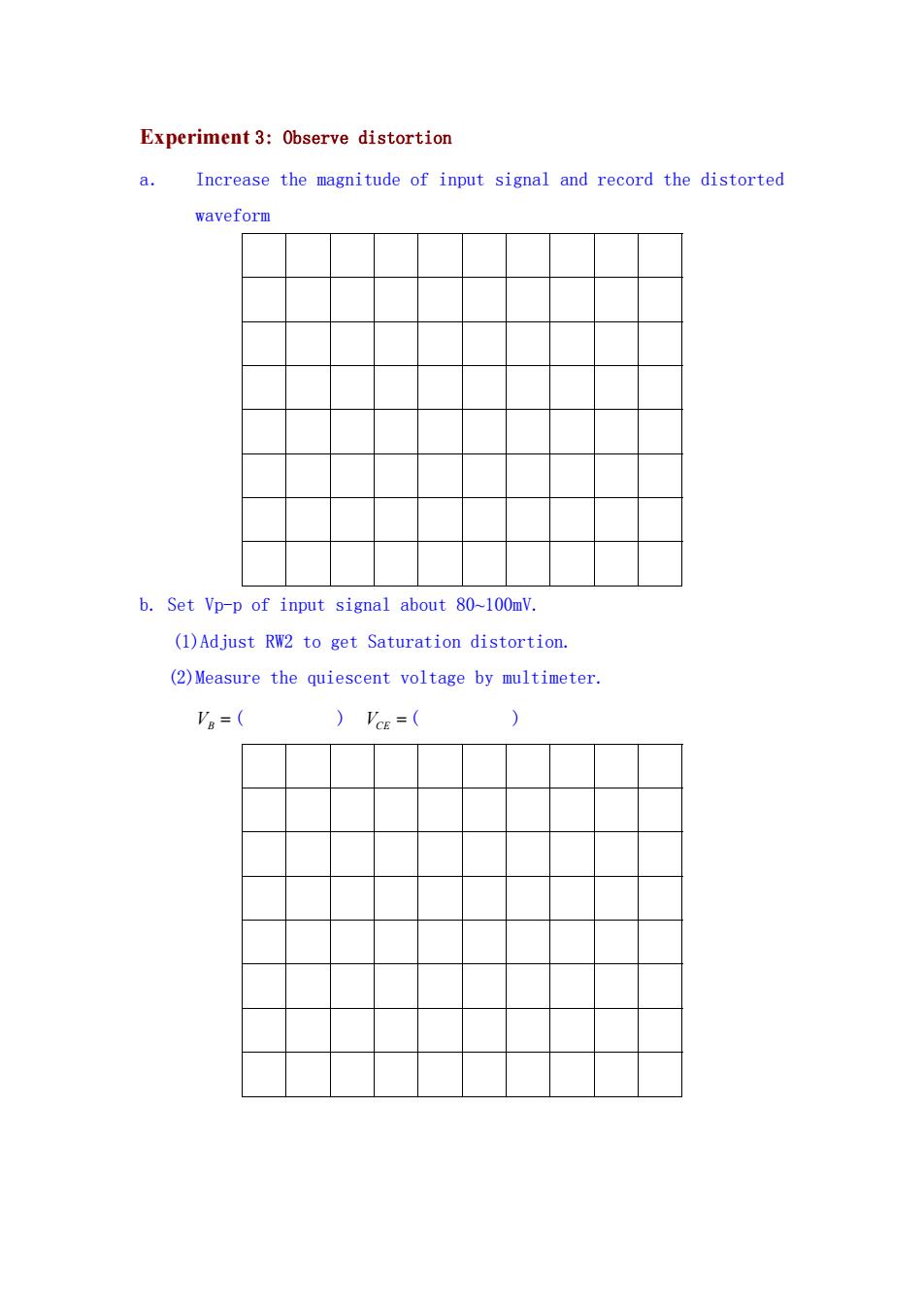
Experiment 3:Observe distortion a. Increase the magnitude of input signal and record the distorted waveform b.Set Vp-p of input signal about 80~100mV. (1)Adjust RW2 to get Saturation distortion. (2)Measure the quiescent voltage by multimeter. Va=( )'cE=(
Experiment 3: Observe distortion a. Increase the magnitude of input signal and record the distorted waveform b. Set Vp-p of input signal about 80~100mV. (1)Adjust RW2 to get Saturation distortion. (2)Measure the quiescent voltage by multimeter. VB ( ) VCE ( )

c.set Vp-p of input signal about 80~120mV. (2)Adjust RW2 to get Cut-off distortion. (3)Measure the quiescent voltage by multimeter. Va=( )'cE=(
c.set Vp-p of input signal about 80~120mV. (2)Adjust RW2 to get Cut-off distortion. (3)Measure the quiescent voltage by multimeter. VB ( ) VCE ( )
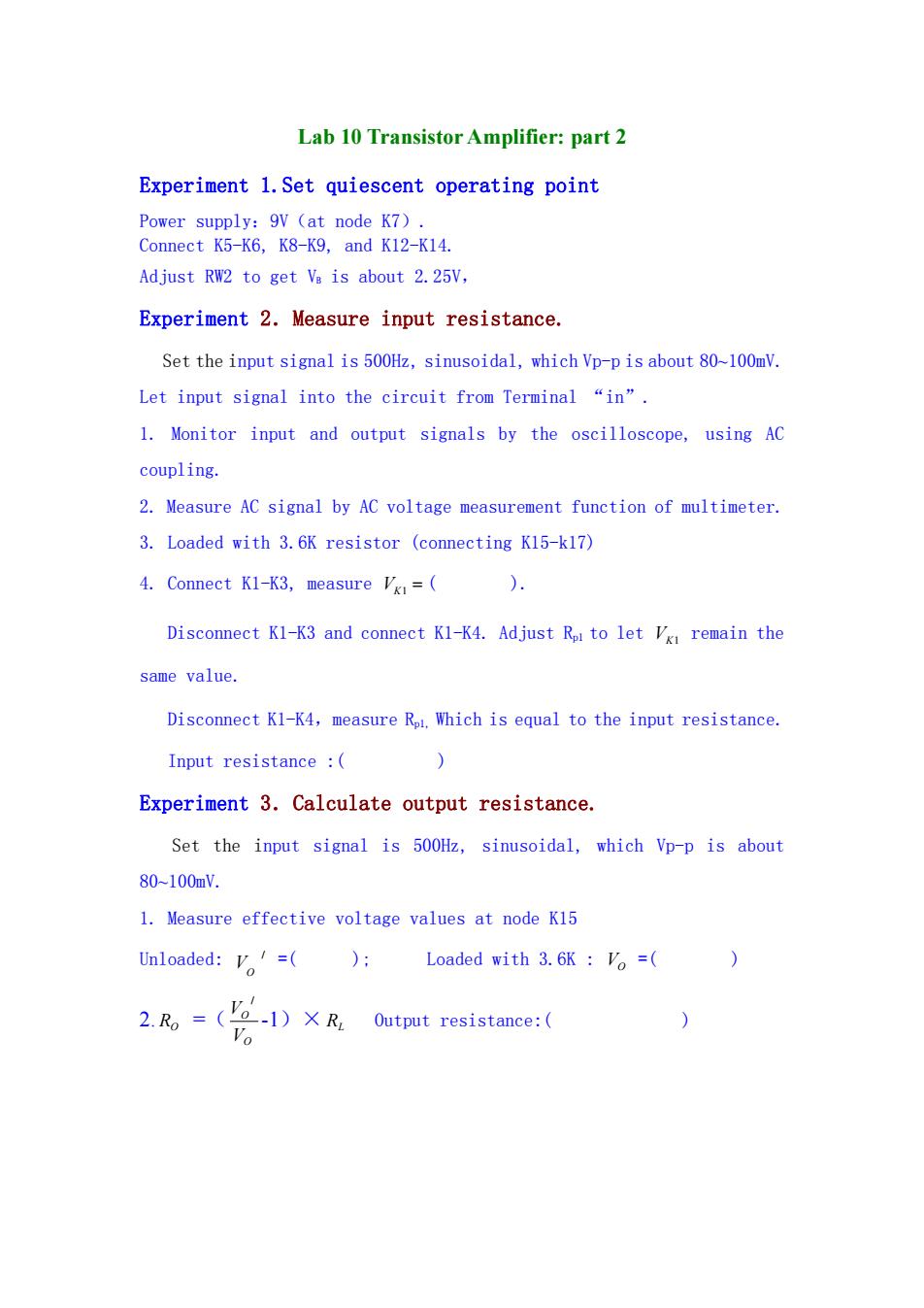
Lab 10 Transistor Amplifier:part 2 Experiment 1.Set quiescent operating point Power supply:9V (at node K7). Connect K5-K6,K8-K9,and K12-K14. Adjust RW2 to get Ve is about 2.25V, Experiment 2.Measure input resistance. Set the input signal is 500Hz,sinusoidal,which Vp-p is about 80~100mV. Let input signal into the circuit from Terminal "in". 1.Monitor input and output signals by the oscilloscope,using AC coupling. 2.Measure AC signal by AC voltage measurement function of multimeter. 3.Loaded with 3.6K resistor (connecting K15-k17) 4.Connect K1-K3,measure V=( ). Disconnect K1-K3 and connect K1-K4.Adjust Rpr to let Vx remain the same value. Disconnect Kl-K4,measure Rp1.Which is equal to the input resistance. Input resistance : ) Experiment 3.Calculate output resistance. Set the input signal is 500Hz,sinusoidal,which Vp-p is about 80-100mV. 1.Measure effective voltage values at node K15 Unloaded:v=(); Loaded with 3.6K Vo=( 0 2.Ro =(-1)XR Output resistance:
Lab 10 Transistor Amplifier: part 2 Experiment 1.Set quiescent operating point Power supply:9V(at node K7). Connect K5-K6, K8-K9, and K12-K14. Adjust RW2 to get VB is about 2.25V, Experiment 2.Measure input resistance. Set the input signal is 500Hz, sinusoidal, which Vp-p is about 80~100mV. Let input signal into the circuit from Terminal “in”. 1. Monitor input and output signals by the oscilloscope, using AC coupling. 2. Measure AC signal by AC voltage measurement function of multimeter. 3. Loaded with 3.6K resistor (connecting K15-k17) 4. Connect K1-K3, measure VK1 ( ). Disconnect K1-K3 and connect K1-K4. Adjust Rp1 to let VK1 remain the same value. Disconnect K1-K4,measure Rp1, Which is equal to the input resistance. Input resistance :( ) Experiment 3.Calculate output resistance. Set the input signal is 500Hz, sinusoidal, which Vp-p is about 80~100mV. 1. Measure effective voltage values at node K15 Unloaded: / O V =( ); Loaded with 3.6K : VO =( ) 2. RO =( O O V V / -1)×RL Output resistance:( )