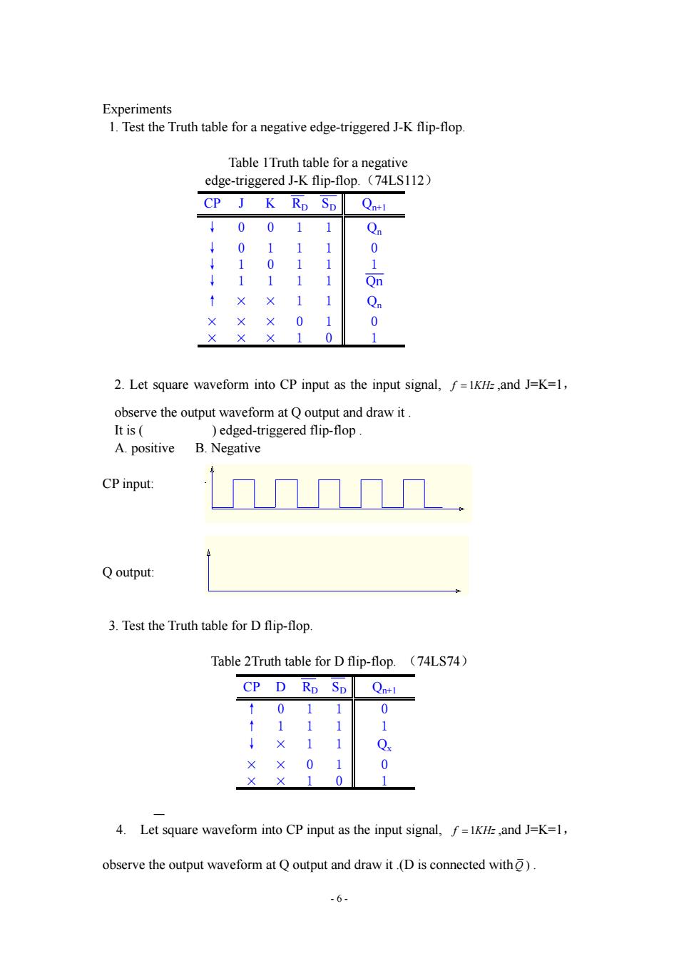
Lab 3 Edged-triggered Flip-Flops Chips information: 1.Dual J-K Negative-edge-triggered Flip-Flops(with Preset and Clear) 贤贵骨滑骨品高問 74LS112 4a⑧ 1CP 1K 1J 1S 1010 20 GND CLK (CP):clock input(negative edge-triggered) J、K: data input Q,0: output CLR (R):direct reset (active-low) PR (5): direct set (active-low) 2.Dual Positive-Edge-Triggered D Flip-Flops 隘滑溫高問福 74LS74 ID ICP IS 1Q IQ GND 3.Combinational logic circuits a风回可可可风 团风2可可可风 色 日 D 时内包内的五 74L001 ,过自山d回 -5-
- 5 - Lab 3 Edged-triggered Flip-Flops Chips information: 1. Dual J-K Negative-edge-triggered Flip-Flops (with Preset and Clear) CLK(CP): clock input(negative edge-triggered) J、K: data input Q,Q : output CLR( R ): direct reset(active-low) PR ( S ): direct set(active-low) 2. Dual Positive-Edge-Triggered D Flip-Flops 3. Combinational logic circuits

Experiments 1.Test the Truth table for a negative edge-triggered J-K flip-flop. Table 1Truth table for a negative edge-triggered J-K flip-flop.(74LS112) CP J K RD SD Qn+l ↓00 1 1 Qn ↓ 0 1 1 1 0 ↓1 0 1 1 ↓ 1 1 Qn ↑ × × 1 1 Qn 0 0 1 0 2.Let square waveform into CP input as the input signal,f=IKH ,and J=K=1, observe the output waveform at Q output and draw it. It is( )edged-triggered flip-flop. A.positive B.Negative CP input: Q output: 3.Test the Truth table for D flip-flop. Table 2Truth table for D flip-flop.(74LS74) CP D Rp Sp Qn+l ↑ 0 1 1 0 ↑11 1 ↓×1 1 Qx 0. 0 1 0 4.Let square waveform into CP input as the input signal,f=IKH,and J=K=1, observe the output waveform at Q output and draw it.(D is connected with). -6-
- 6 - Experiments 1. Test the Truth table for a negative edge-triggered J-K flip-flop. Table 1Truth table for a negative edge-triggered J-K flip-flop. (74LS112) CP J K RD SD Qn+1 ↓0 0 1 1 Qn ↓0 1 1 1 0 ↓1 0 1 1 1 ↓1 1 1 1 Qn ↑ × × 1 1 Qn ××× 01 0 ××× 10 1 2. Let square waveform into CP input as the input signal, f 1KHz ,and J=K=1, observe the output waveform at Q output and draw it . It is ( ) edged-triggered flip-flop . A. positive B. Negative CP input: Q output: 3. Test the Truth table for D flip-flop. Table 2Truth table for D flip-flop. (74LS74) CP D RD SD Qn+1 ↑0 1 1 0 ↑1 1 1 1 ↓ × 1 1 Qx × × 01 0 × × 10 1 4. Let square waveform into CP input as the input signal, f 1KHz ,and J=K=1, observe the output waveform at Q output and draw it .(D is connected with Q )

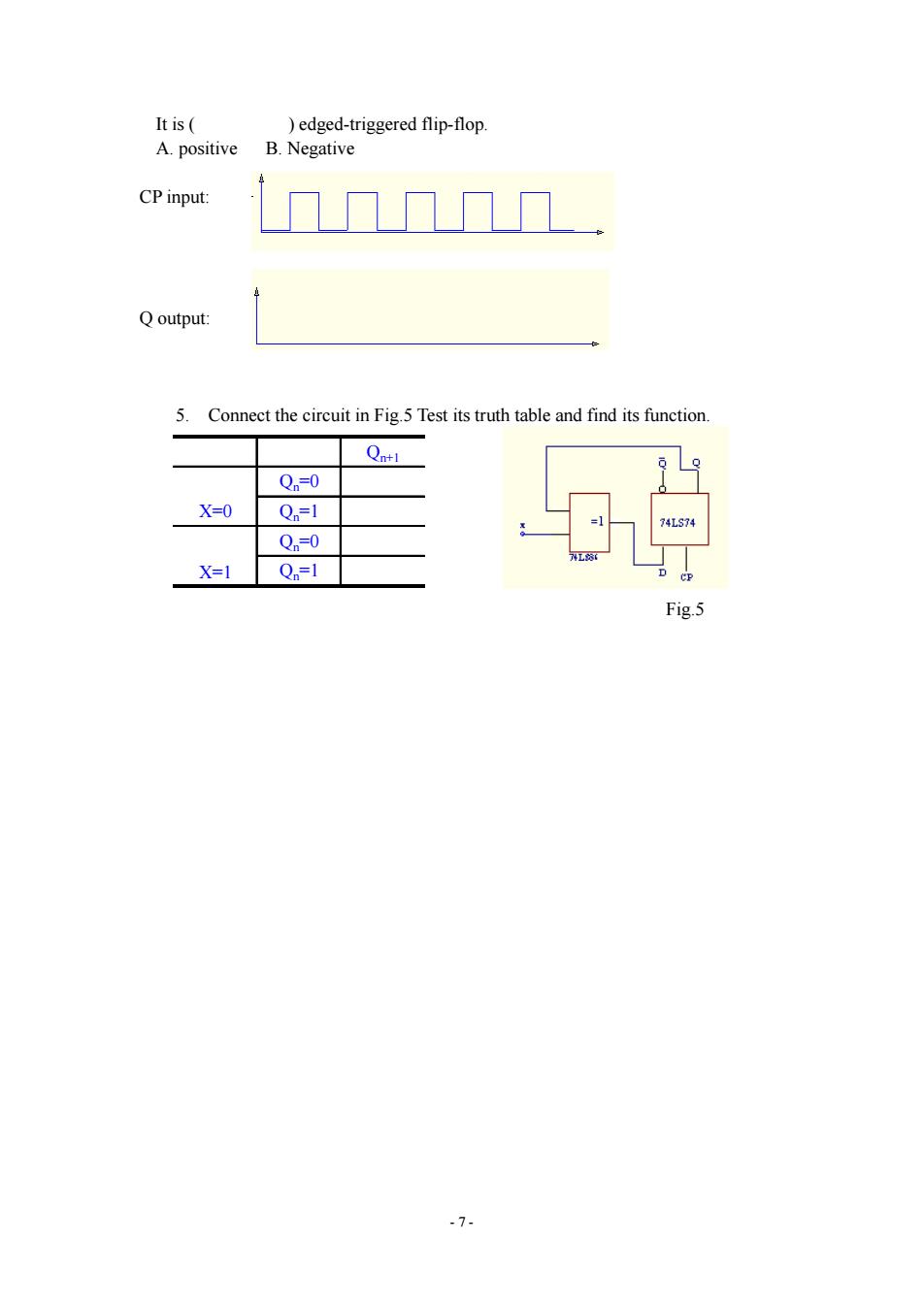
It is( )edged-triggered flip-flop A.positive B.Negative CP input: Q output: 5. Connect the circuit in Fig.5 Test its truth table and find its function Qnt1 Qn=0 X=0 Qn=1 =1 74LS74 Q=0 X=1 Qn=1 P Fig.5 -7-
- 7 - It is ( ) edged-triggered flip-flop. A. positive B. Negative CP input: Q output: 5. Connect the circuit in Fig.5 Test its truth table and find its function. Qn+1 Qn=0 Qn=1 Qn=0 Qn=1 X=0 X=1 Fig.5