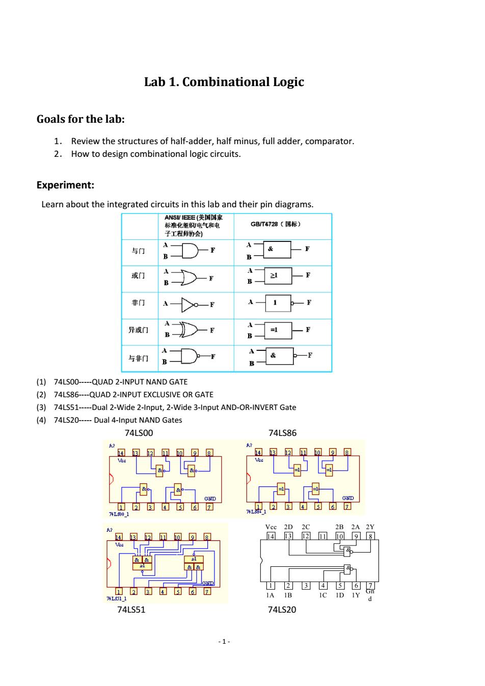
Lab 1.Combinational Logic Goals for the lab: 1.Review the structures of half-adder,half minus,full adder,comparator. 2.How to design combinational logic circuits. Experiment: Learn about the integrated circuits in this lab and their pin diagrams. ANSI IEEE(美国国家 标准化侄织电气和电 G8/T4728(国标) 子工程师协会) A 与门 或门 A ≥1 B B- 非门 异或门 与非门 (1)74LS00-----QUAD 2-INPUT NAND GATE (2)74LS86----QUAD 2-INPUT EXCLUSIVE OR GATE (3)74LS51-----Dual 2-Wide 2-Input,2-Wide 3-Input AND-OR-INVERT Gate (4)74LS20-----Dual 4-Input NAND Gates 74LS00 74LS86 风风回可可可同 74L9001 日百西日可回 A? Vee 2D 2B 2A 2Y 4国2回回98 立中可 山246可 Gn 7L11 1A IB IC ID IY d 74LS51 74LS20 -1-
‐ 1 ‐ Lab 1. Combinational Logic Goals for the lab: 1. Review the structures of half‐adder, half minus, full adder, comparator. 2. How to design combinational logic circuits. Experiment: Learn about the integrated circuits in this lab and their pin diagrams. (1) 74LS00‐‐‐‐‐QUAD 2‐INPUT NAND GATE (2) 74LS86‐‐‐‐QUAD 2‐INPUT EXCLUSIVE OR GATE (3) 74LS51‐‐‐‐‐Dual 2‐Wide 2‐Input, 2‐Wide 3‐Input AND‐OR‐INVERT Gate (4) 74LS20‐‐‐‐‐ Dual 4‐Input NAND Gates 74LS00 74LS86 74LS51 74LS20 1 2 3 4 5 6 7 14 13 12 11 10 9 8 Vcc Gn d 1A 1Y 1B 1C 1D 2D 2A 2C 2B 2Y & &

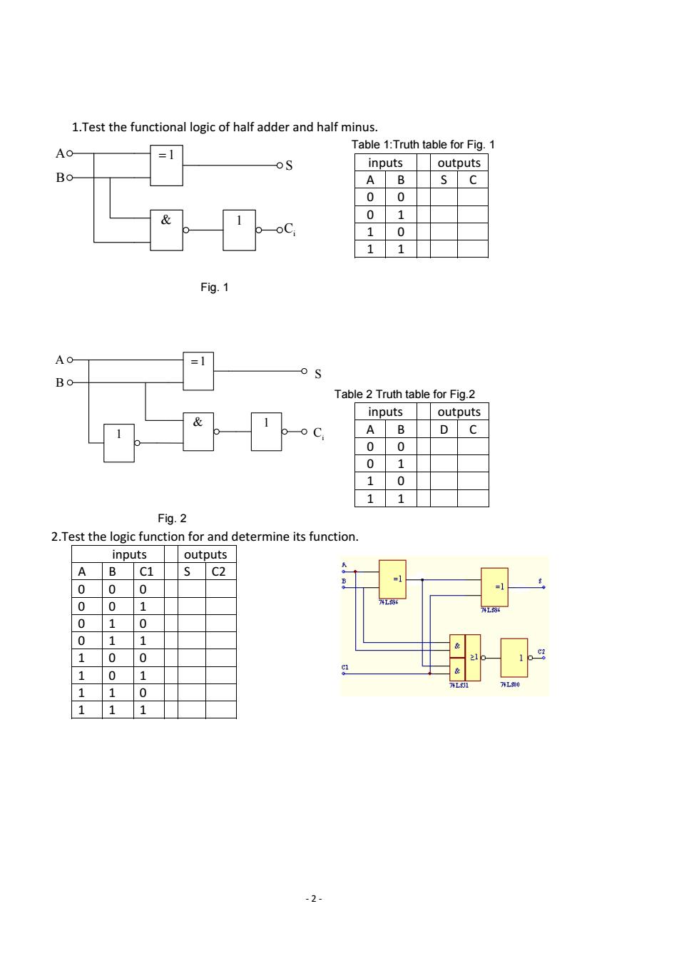
1.Test the functional logic of half adder and half minus. Table 1:Truth table for Fig.1 Ao =1 oS inputs outputs Bo AB s C 0 & 0 1 oC 1 0 1 Fig.1 Ao =1 Bo Table 2 Truth table for Fig.2 inputs outputs A 0 0 0 1 1 0 1 1 Fig.2 2.Test the logic function for and determine its function. inputs outputs SC2 =1 00 0 00 1 工8 01 0 01 1 10 0 101 40 11 0 11 1 -2-
‐ 2 ‐ 1.Test the functional logic of half adder and half minus. 1 & 1 A B S Ci Fig. 1 Table 1:Truth table for Fig. 1 inputs outputs A B S C 0 0 0 1 1 0 1 1 1 & 1 A B 1 S Ci Fig. 2 Table 2 Truth table for Fig.2 inputs outputs A B D C 0 0 0 1 1 0 1 1 2.Test the logic function for and determine its function. inputs outputs A B C1 S C2 0 0 0 0 0 1 0 1 0 0 1 1 1 0 0 1 0 1 1 1 0 1 1 1

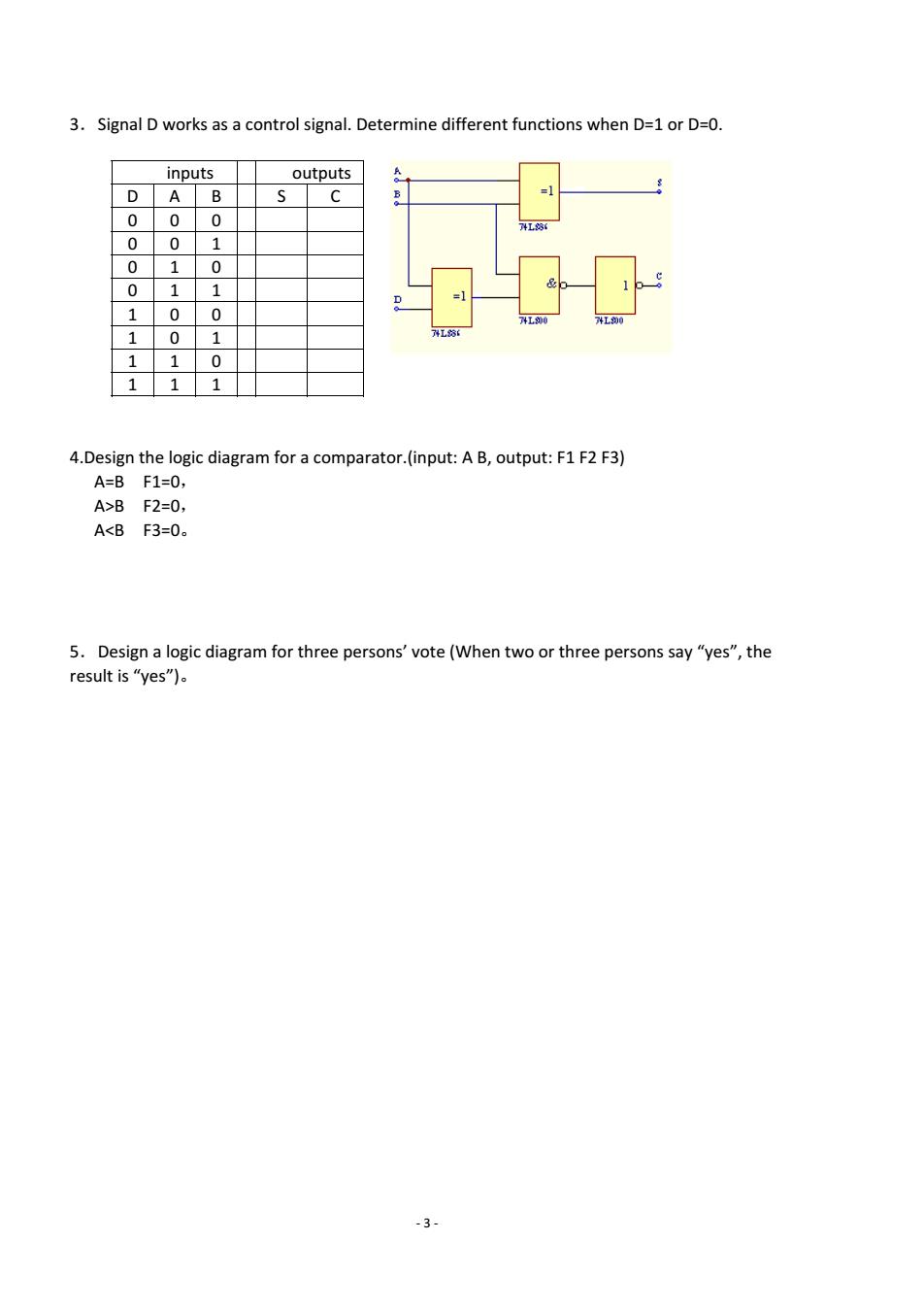
3.Signal D works as a control signal.Determine different functions when D=1 or D=0. inputs outputs D AB C =1 0 0 0 0 0 1 0 1 0 0 1 1 0 0 400 1 0 1 1 1 0 1 1 1 4.Design the logic diagram for a comparator.(input:A B,output:F1 F2 F3) A=BF1=0, A>BF2=0, A<BF3=0。 5.Design a logic diagram for three persons'vote (When two or three persons say "yes",the result is"yes")。 -3-
‐ 3 ‐ 3.Signal D works as a control signal. Determine different functions when D=1 or D=0. inputs outputs D A B S C 0 0 0 0 0 1 0 1 0 0 1 1 1 0 0 1 0 1 1 1 0 1 1 1 4.Design the logic diagram for a comparator.(input: A B, output: F1 F2 F3) A=B F1=0, A>B F2=0, A<B F3=0。 5.Design a logic diagram for three persons’ vote (When two or three persons say “yes”, the result is “yes”)