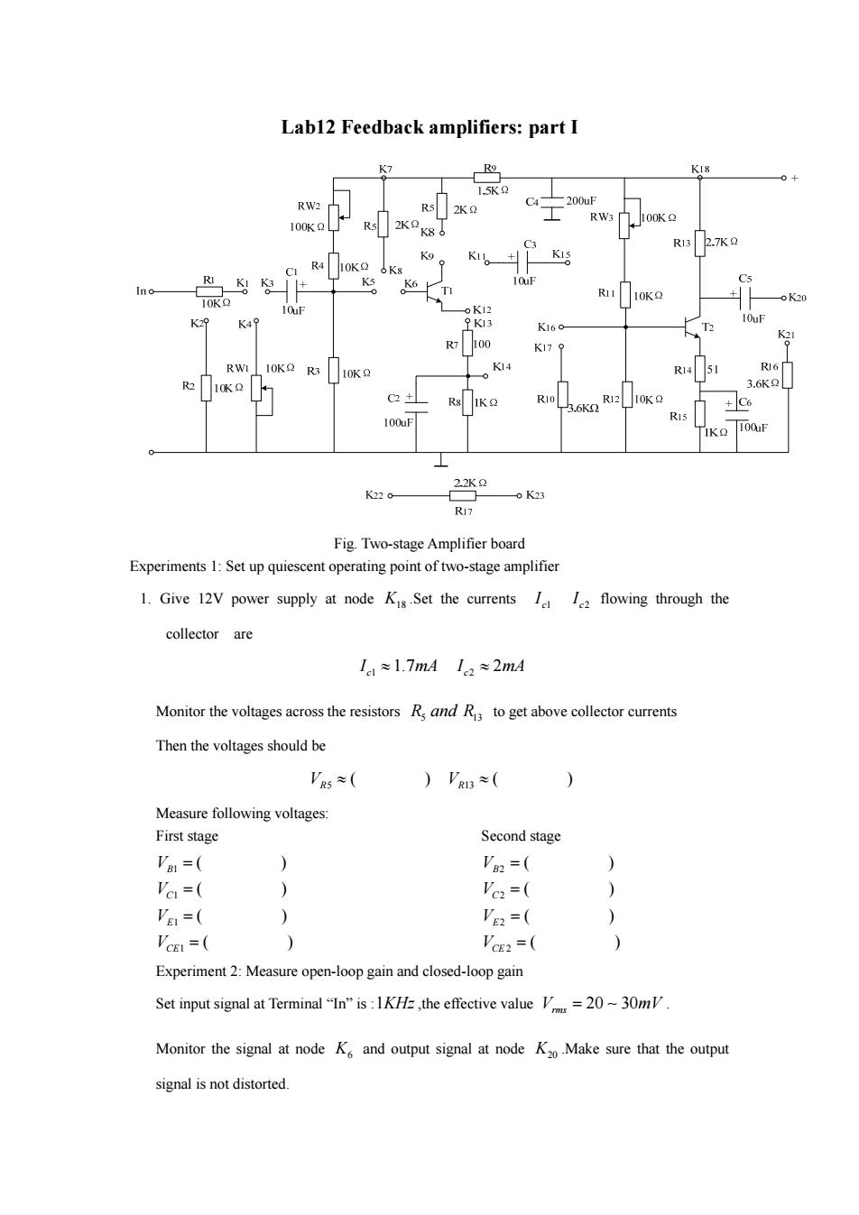
Labl2 Feedback amplifiers:part I K7 R9 K18 0+ 5K2 RW2 200uF 2K2 R W I00K2 100K2 R13 2.7K2 R4 RI K3+ K5 Cs no R11 + 10K2 10K2 oK12 K29 K49 9K13 10uF K16o K21 R7 00 K179 RWI 10KQ R3 10K2 K14 R1451 R16 R2 10K2 3.6K2 C2 R10 R12 10K2 3.6K2 +C6 100uF R15 1KO 100uF 2.2K2 K220- 0K23 Ri7 Fig.Two-stage Amplifier board Experiments 1:Set up quiescent operating point of two-stage amplifier 1.Give 12V power supply at node Kis.Set the currents Ie I2 flowing through the collector are I≈1.7mA1c2≈2mA Monitor the voltages across the resistors R and R to get above collector currents Then the voltages should be 'R5≈( )'RI3≈( ) Measure following voltages: First stage Second stage Va1=( ) V2=( 'c=( 1 Vc2=( ) VE=( ) VE2=( ) VCEI = ) VE2=( Experiment 2:Measure open-loop gain and closed-loop gain Set input signal at Terminal "In"is:1KH=,the effective value V=20~30m Monitor the signal at node K and output signal at node K2Make sure that the output signal is not distorted
Lab12 Feedback amplifiers: part I Fig. Two-stage Amplifier board Experiments 1: Set up quiescent operating point of two-stage amplifier 1. Give 12V power supply at node K18 .Set the currents c1 I c2 I flowing through the collector are 1 2 1.7 2 c c I mA I mA Monitor the voltages across the resistors R5 13 and R to get above collector currents Then the voltages should be 5 13 ( )( ) V V R R Measure following voltages: First stage 1 1 1 1 ( ) ( ) ( ) ( ) B C E CE V V V V Second stage 2 2 2 2 ( ) ( ) ( ) ( ) B C E CE V V V V Experiment 2: Measure open-loop gain and closed-loop gain Set input signal at Terminal “In” is :1KHz,the effective value 20 30 V mV rms . Monitor the signal at node K6 and output signal at node K20 .Make sure that the output signal is not distorted

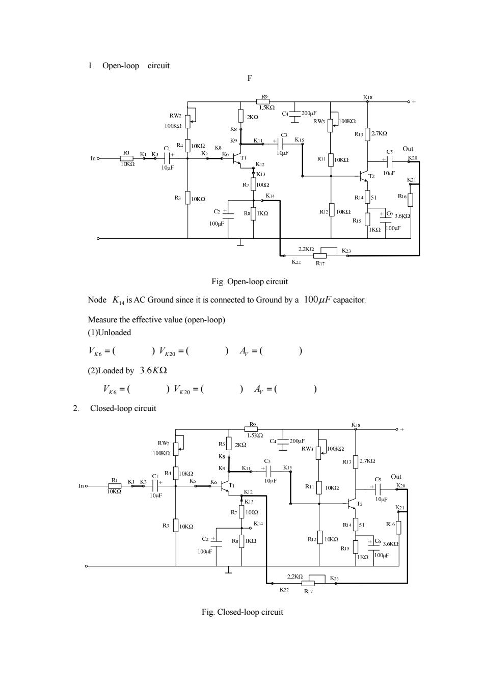
1.Open-loop circuit K18 RW2 00l RW 100K2 100K2 R13 27K2 C R41K2 Out K 10K2 20 10K K13 21 1002 R3 10K2 K14 R14 R6 C2+ R1210K2 +C63.6K2 100uF 1K 100uF 2.2K2— K23 K22 R17 Fig.Open-loop circuit Node K is AC Ground since it is connected to Ground by a 100uF capacitor. Measure the effective value (open-loop) (1)Unloaded Vx6=( )'x20=( )A=( ) (2)Loaded by 3.6K Vk6=( )'k20=( )A=( 2. Closed-loop circuit Ro K18 1.5K2 RW2 C4 R5 2K2 -200uF RV3■ 100K2 100K2 R13 2.7K2 K15 C R4 10K2 Out RI K5 Ino- KK3 K6 R11 10K2 K0 10gF K12 K13 T2 K21 1002 R3 10K2 K14 R451 R16 C2+ R✉K R1210K2 +C63.6K2 100,uF R15 1K2 100uF 22K2K23 K22 RI7 Fig.Closed-loop circuit
1. Open-loop circuit F Fig. Open-loop circuit Node K14 is AC Ground since it is connected to Ground by a 100F capacitor. Measure the effective value (open-loop) (1)Unloaded 6 20 ( )( )( ) VV A KK V (2)Loaded by 3.6K 6 20 ( )( )( ) VV A KK V 2. Closed-loop circuit Fig. Closed-loop circuit

Define the feedback configuration.Choose from series-shunt feedback,series-series feedback, shunt-shunt feedback and shunt-series feedback Feedback configuration: Measure the effective value closed-loop) (1)Unloaded Vk6=( )'x20=( )A=( ) (2)Loaded by 3.6K Vx6=( )Vk20=( )4=( 3.Stability of A Decrease supply voltage to 10V.Compare change of 4 of open-loop circuit and in closed-loop circuit. Power supply 4 (open-loop) 4(closed-loop) 12V 10V
Define the feedback configuration. Choose from series-shunt feedback, series-series feedback, shunt-shunt feedback and shunt-series feedback Feedback configuration: Measure the effective value ( closed- loop) (1)Unloaded 6 20 ( )( )( ) VV A KK V (2)Loaded by 3.6K 6 20 ( )( )( ) VV A KK V 3. Stability of AV Decrease supply voltage to 10V. Compare change of AV of open-loop circuit and in closed-loop circuit. Power supply AV (open-loop) AV (closed-loop) 12V 10V

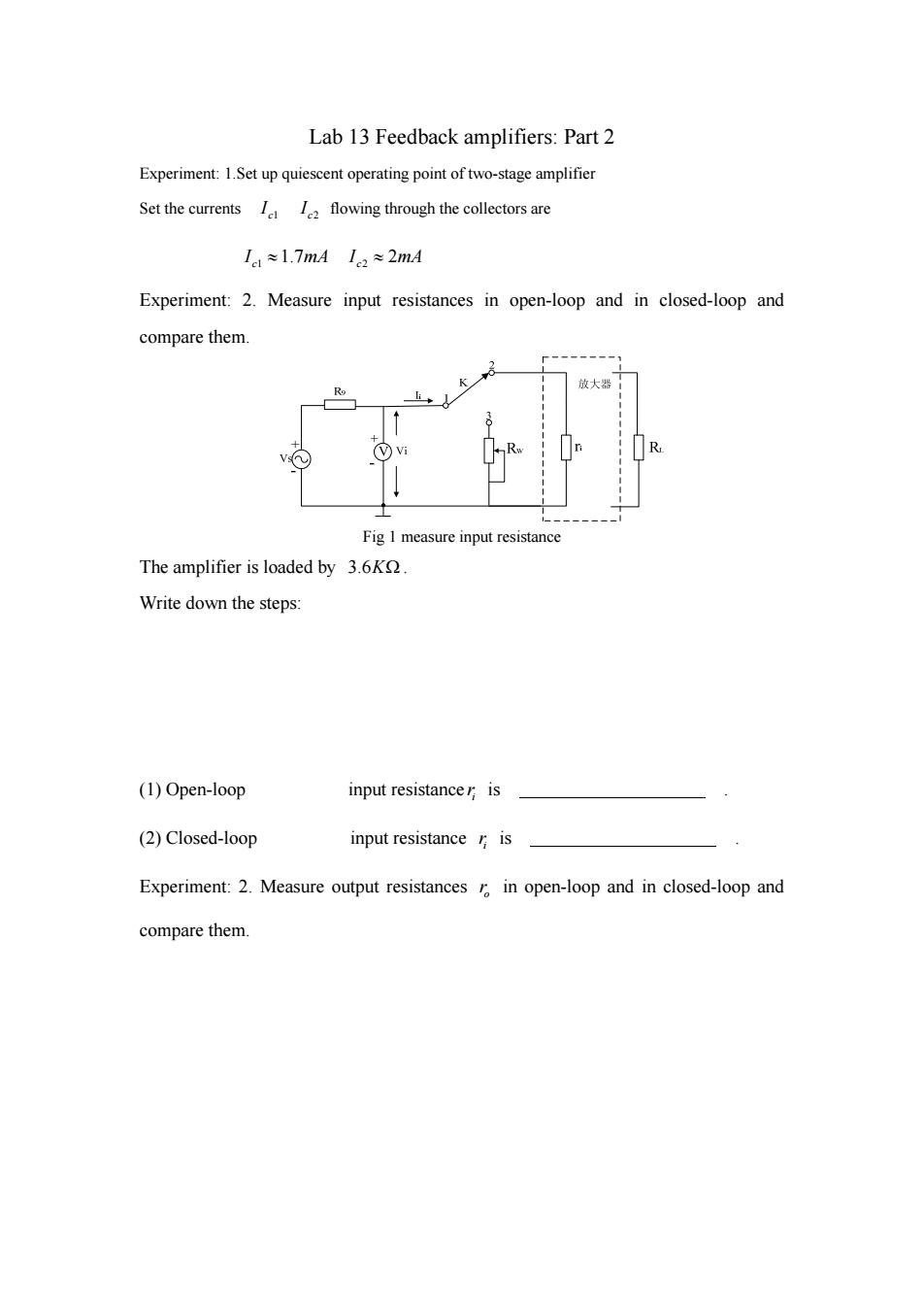
Lab 13 Feedback amplifiers:Part 2 Experiment:1.Set up quiescent operating point of two-stage amplifier Set the currents I flowing through the collectors are 11≈1.7mAIc2≈2mA Experiment:2.Measure input resistances in open-loop and in closed-loop and compare them. 放大器 Vi R R Fig I measure input resistance The amplifier is loaded by 3.6K Write down the steps: (1)Open-loop input resistancer is (2)Closed-loop input resistance r is Experiment:2.Measure output resistances r in open-loop and in closed-loop and compare them
Lab 13 Feedback amplifiers: Part 2 Experiment: 1.Set up quiescent operating point of two-stage amplifier Set the currents c1 I c2 I flowing through the collectors are 1 2 1.7 2 c c I mA I mA Experiment: 2. Measure input resistances in open-loop and in closed-loop and compare them. Fig 1 measure input resistance The amplifier is loaded by 3.6K . Write down the steps: (1) Open-loop input resistance i r is . (2) Closed-loop input resistance i r is . Experiment: 2. Measure output resistances o r in open-loop and in closed-loop and compare them

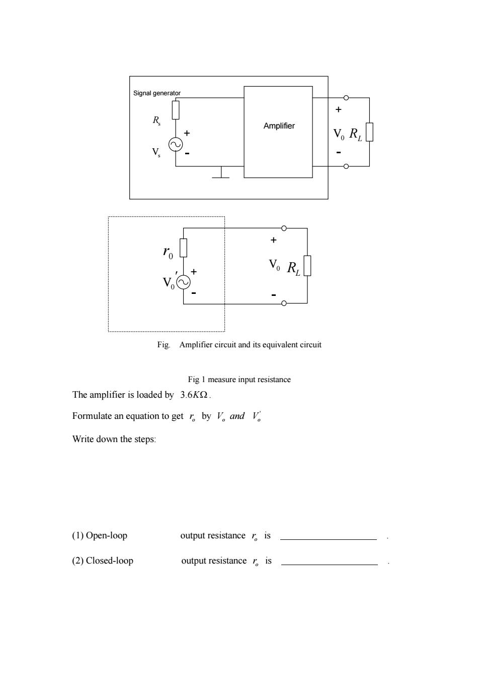
Signal generator R Amplifier + V。R + 0 Vo Ri Fig.Amplifier circuit and its equivalent circuit Fig I measure input resistance The amplifier is loaded by 3.6K Formulate an equation to get by V and V Write down the steps: (1)Open-loop output resistance r is (2)Closed-loop output resistance r is
+ RL + Amplifier Signal generator Rs Vs V0 V0 0 r + RL V0 + Fig. Amplifier circuit and its equivalent circuit Fig 1 measure input resistance The amplifier is loaded by 3.6K . Formulate an equation to get o r by ' V and V o o Write down the steps: (1) Open-loop output resistance o r is . (2) Closed-loop output resistance o r is