正在加载图片...
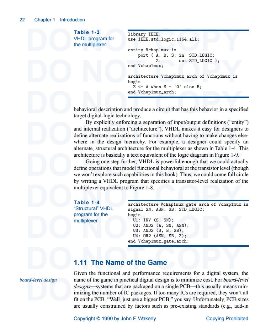
22 Chapter 1 Introduction Table 1-3 VHDL program for the multiplexer entity Vchapimux is port A,B,S:in STD_LOGIC: 7: out STD_LOGIC ) end Vchapimux; architecture Vchapimux_arch of Vchapimux is begin A when S0 else B; end Vchapimux_arch; behavioral description and produce a circuit that has this behavior in a specified target digital-logi c technology By explicitly enforcing a separation of input/output definitions("entity") and internal realization("architecture"),VHDL makes it easy for designers to define alternate realizations of functions without having to make changes else- where in the design hierarchy. For example,a designer could specify an alternate,structural architecture for the multiplexer as shown in Table 1-4.This architecture is basically a text equivalent of the logic diagram in Figure 1-9. Going one step further,VHDL is powerful enough that we could actually define operations that model functional behavioral at the transistor level (though we won't explore such capabilities in this book).Thus,we could come full circle Table 1-4 architecture Vchapimux rch of Vchapimux is "Structural"VHDL signal SN,ASN,SB:STD LOGIC: program for the begin multiplexer. U1:INV (S,SN); _gate_arch 1.11 The Name of the Game Given the functional and performance requirements for a digital system,the board-level design name of the game in practical digital design is to minimize cost.For board-level designs-systems that are packaged on a single PCB-this usually means min- ber of IC packages.If too many ICs are required,they we on't all fit on the PCB."Well,just use a bigger PCB,"you say.Unfortunately,PCB sizes are usually constrained by factors such as pre-existing standards (e.g.,add-in Copyright1999 by John F.Wakerly Copying Prohibited 22 Chapter 1 Introduction DO NOT COPY DO NOT COPY DO NOT COPY DO NOT COPY DO NOT COPY DO NOT COPY DO NOT COPY DO NOT COPY DO NOT COPY Copyright © 1999 by John F. Wakerly Copying Prohibited behavioral description and produce a circuit that has this behavior in a specified target digital-logic technology. By explicitly enforcing a separation of input/output definitions (“entity”) and internal realization (“architecture”), VHDL makes it easy for designers to define alternate realizations of functions without having to make changes elsewhere in the design hierarchy. For example, a designer could specify an alternate, structural architecture for the multiplexer as shown in Table 1-4. This architecture is basically a text equivalent of the logic diagram in Figure 1-9. Going one step further, VHDL is powerful enough that we could actually define operations that model functional behavioral at the transistor level (though we won’t explore such capabilities in this book). Thus, we could come full circle by writing a VHDL program that specifies a transistor-level realization of the multiplexer equivalent to Figure 1-8. 1.11 The Name of the Game Given the functional and performance requirements for a digital system, the name of the game in practical digital design is to minimize cost. For board-level designs—systems that are packaged on a single PCB—this usually means minimizing the number of IC packages. If too many ICs are required, they won’t all fit on the PCB. “Well, just use a bigger PCB,” you say. Unfortunately, PCB sizes are usually constrained by factors such as pre-existing standards (e.g., add-in Table 1-3 VHDL program for the multiplexer. library IEEE; use IEEE.std_logic_1164.all; entity Vchap1mux is port ( A, B, S: in STD_LOGIC; Z: out STD_LOGIC ); end Vchap1mux; architecture Vchap1mux_arch of Vchap1mux is begin Z <= A when S = '0' else B; end Vchap1mux_arch; Table 1-4 “Structural” VHDL program for the multiplexer. architecture Vchap1mux_gate_arch of Vchap1mux is signal SN, ASN, SB: STD_LOGIC; begin U1: INV (S, SN); U2: AND2 (A, SN, ASN); U3: AND2 (S, B, SB); U4: OR2 (ASN, SB, Z); end Vchap1mux_gate_arch; board-level design